Viking Pump TSM341.1: SG Mag Drive Series User Manual
Page 9
SECTION TSM 341.1
ISSUE
J
PAGE 9 OF 19
SG-804, -805 & -807
PUMP DISASSEMBLY
Before attempting to repair the pump, make sure that all of
the details covered in “
TROUBLESHOOTING” on page 16
have been checked out because disassembly of a good
pump should be avoided. Due to pump construction and close
tolerances used in the pump manufacture, repair is seldom
economically feasible, unless it is an O-ring or such. Often
when some internal part wears such as a bushing, shaft or
gear, it will cause excessive wear in other mating parts. In
this case more components will be required to rebuild the
pump back to original condition than originally expected.
Replacement parts are only available as displayed in the
table of parts (
Figure 14 & Figure 15, Table 3). Contact
your local distributor to obtain replacement parts. Be sure
to supply the pump model number and serial number.
Mark all sections of the pump during disassembly to ensure
they will be reassembled in the proper order and orientation.
Note: The pump must be separated from coupling to
disassemble (See “
COUPLING DISASSEMBLY” on page 7).
1. Remove the assembly capscrews (item 8, Figure 14
or 15).
2. Remove the key and the second retaining ring from the
driver shaft.
3. The pump is now held together only by the alignment
sleeves. Hold the head of the pump and gently tap on
the sides of the pump bracket with a soft face hammer,
alternating sides of the pump. This should slowly
separate the sections. Do not hit the sections hard or
use a screwdriver to pry them apart as this may damage
the mating surfaces.
4. After the pump is apart, inspect all parts for signs of
wear. Look carefully at the shaft, bushings, inside of
casing, gear teeth, and the flat sections that are located
on each side of the casing for sign of wear.
5. Visually inspect the bracket O-ring but do not remove
it unless planning to replace, especially if it is an
encapsulated O-ring. If the O-ring located between the
sections are PTFE (appear to be white), it is strongly
recommended to replace rather than reuse.
6. Remove the acorn nut covering the relief valve adjusting
screw. Measure the distance of the relief valve adjusting
screw to the pump surface and record its length. Finish
disassembling the relief valve and inspect the seat in the
head and the poppet for signs of wear or foreign matter
on either surface.
SG-804, -805 & -807
PUMP ASSEMBLY
•
The pump is ready to be reassembled after all parts
have been changed and worn parts replaced.
•
Use a suitable lubricant compatible with the fluid being
handled when reassembling the pump.
•
Make sure all holes machined in the bracket are clean
and that the mating surfaces of each section are free of
any dents or burrs. Make sure the hole in the end of the
shaft is unrestricted.
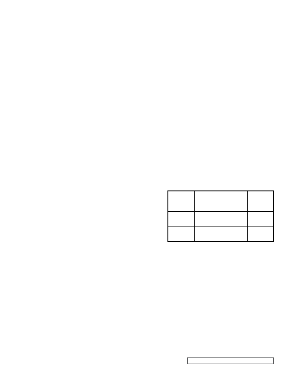
MODEL
BOLT SIZE
QUANTITY
TORQUE
SPEC.
(FT-LB)
SG-804
SG-805
¼
2
7-9
SG-807
½
4
50-55
6. Reassemble the relief valve, setting the adjusting
screw to the previous dimension. Place the gasket
onto the adjusting screw holding the adjusting screw
while tightening the locknut. Recheck the dimension,
install the second gasket on other side of the locknut
and install the acorn nut.
7. Install the drive key into the drive shaft keyset and the
inner retaining ring into the groove closest to the pump
bracket.
1. Install the bracket O-ring. If it is encapsulated (purple or
orange appearance) then follow the special instructions
below.
Do not attempt to reuse this type of O-ring if it has been
removed. Immerse a new O-ring in boiling water for
a few minutes. Remove from water and stretch out in
hands so it will fit onto the bracket hub without forcing
over a sharp edge. When in place, run hot water over
O-ring until it shrinks down tight into the hub O-ring
groove. Dry the area with compressed air.
2. Place head down on flat surface with the O-ring groove
up and place the O-ring into the groove. Install the
alignment sleeves in proper holes by tapping with soft
face hammer.
3. Slide the next section onto the alignment sleeves,
whether it is a separation plate or a casing and install
another O-ring. The pump may require more than one
pair of alignment sleeves: add additional pairs when
necessary.
4. After the casing is installed, place the driver and driven
gears and shaft into the proper positions (refer to
Figure 14 & 15) for proper positioning of driver and
driven shaft assemblies.
5. After installing the casing, there should be a short
length of alignment sleeve projecting out to line up
the bracket. Install the final O-ring between sections;
lubricate the gears and shafts, then slide the bracket
into place. Turn the pump on its side and insert
assembly capscrew and tighten each capscrew until
finger tight. Tighten with torque wrench as specified
below: