Md-a & md-b coupling pump removal, Caution, Danger – Viking Pump TSM341.1: SG Mag Drive Series User Manual
Page 7
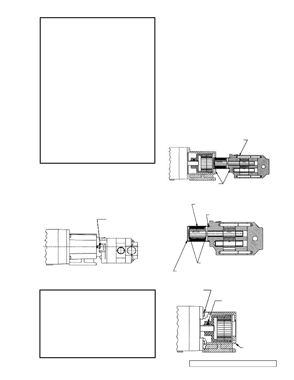
INNER MAGNET ASSEMBLY
STATIC CANISTER O-RING
RETAINING
RINGS
CANISTER
SETSCREWS
(2) REQUIRED
CAPSCREWS
(4) REQUIRED
BRACKET
PLACE HANDS BACK HERE
DO NOT PLACE
FINGERS HERE
SECTION TSM 341.1
ISSUE
J
PAGE 7 OF 19
BRACKET CAPSCREWS
MD-A & MD-B COUPLING
PUMP REMOVAL
Read all of the instructions before proceeding with
disassembly of the coupling and/or pump.
1. Remove piping from the ports and remove the mounting
capscrews securing the pump to the bracket (See
Figure 9). Support larger pumps with an overhead hoist
if possible.
2. The canister will probably be full of liquid. Use care while
removing from the pump and pull straight off. Remove
the external snap ring (closest to end of shaft) and slide
off the inner magnet assembly (See
Figure 11). Use
caution, as this is a very strong magnet.
3. Do not remove the canister O-ring unless it is damaged,
especially if it is PTFE (Derivative) Encapsulated. If a
new O-ring is required, follow instructions in the
PUMP
ASSEMBLY section, page 10.
4. You should be able to visually inspect the outer magnets
from the end of the bracket. If removal is necessary,
start by removing the (4) capscrews and separating
the bracket from the motor or bearing carrier (See
Figure 12). Loosen setscrews in outer magnet assembly
to pull assembly off shaft. If the unit features a bearing
carrier, the bearings should not require maintenance
since they are sealed. If necessary, disassemble
by removing the single internal retaining ring (See
Figure 8) then press the shaft and bearings out of the
housing. Remove the external retaining rings from the
shaft to remove bearings.
FIGURE 9
FIGURE 10
FIGURE 11
CAUTION !
Use extreme caution, when pulling the inner
magnet away from the outer magnet (See
Figure 18, page 11). Do not place your fingers
between the pump mounting flange and the
face of the bracket. If you do not completely
pull the pump out it will snap back and could
pinch a finger or hand. Once the inner magnet
is removed from the bracket be careful setting
it down as it will attract any iron or steel object.
(2) Required for SG-807 with MD-A Coupling
(4) REQUIRED FOR ALL SG-804 & SG-805, & SG-807 WITH
MD-B COUPLING
FIGURE 12
DANGER !
Before opening any Viking pump liquid
chamber (pumping chamber, reservoir, relief
valve adjusting cap fitting etc.) Be sure:
1. That any pressure in the chamber has
been completely vented through the
suction or discharge lines or other
appropriate openings or connections.
2. That the driving means (motor, turbine,
engine, etc.) has been “locked out” or
made non- operational so that it cannot
be started while work is being done on
pump.
3. That you know what liquid the pump
has been handling and the precautions
necessary to safely handle the liquid.
Obtain a material safety data sheet
(MSDS) for the liquid to be sure these
precautions are understood.
Failure to follow above listed precautionary
measures may result in serious injury or
death.