Mounting, Piping/hose, General cont’d – Viking Pump TSM341.1: SG Mag Drive Series User Manual
Page 4: Alignment
S
D
S
D
S
D
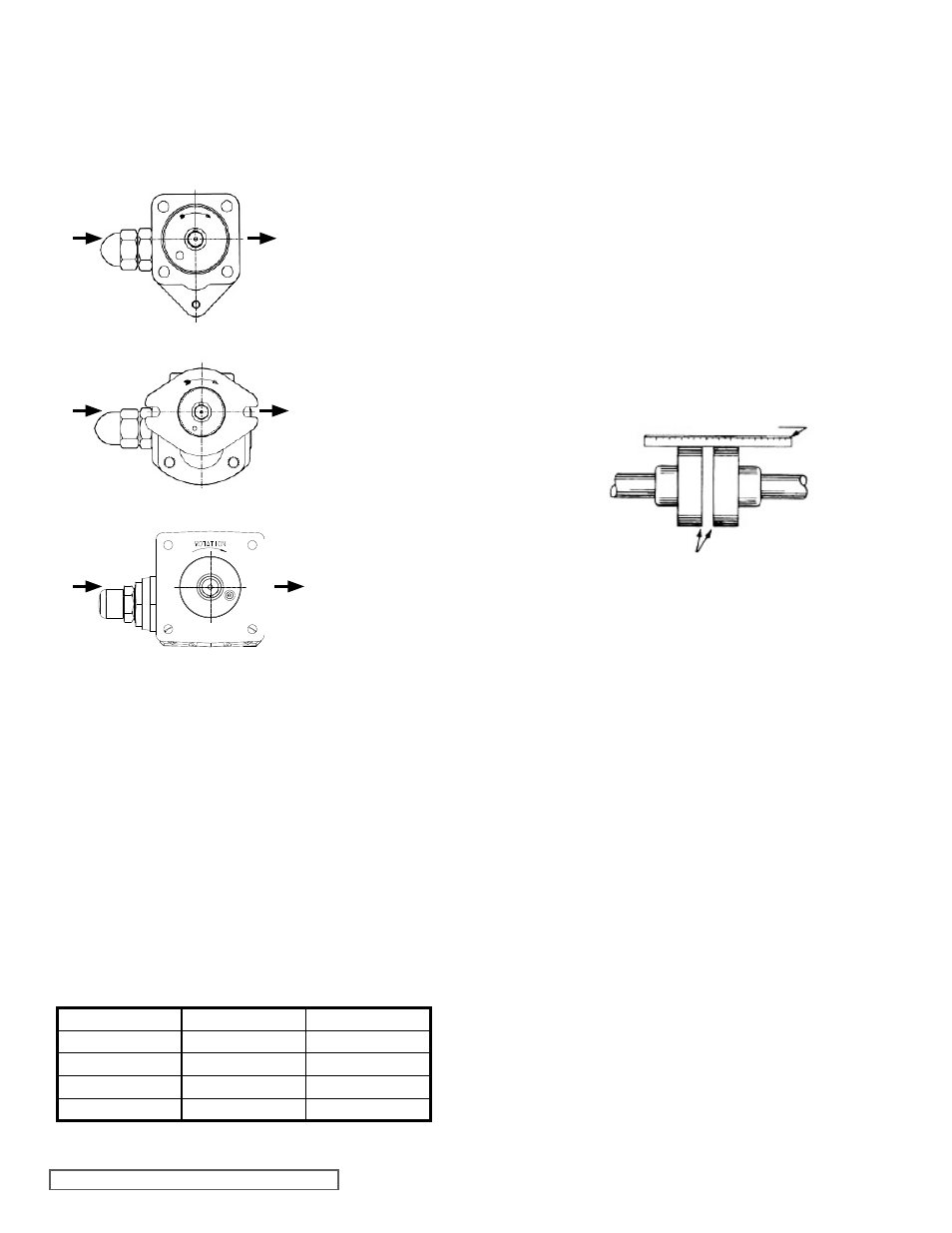
USE STRAIGHT EDGE. THESE SURFACES MUST BE PARALLEL
CHECK WIDTH BETWEEN THESE
SURFACES WITH INSIDE CALIPERS TO BE
CERTAIN THE FACES ARE EQUAL DISTANCE
APART AND PARALLEL
COUPLING
ALIGNMENT
FIGURE 6
SECTION TSM 341.1
ISSUE
J
PAGE 4 OF 19
Mounting
When using an M drive configuration, alignment is insured
by the coupling bracket. If the unit features a bearing carrier,
then a flexible coupling will be required and care should be
given to properly align the bearing carrier to the motor. See
“
Alignment” on this page.
Since the magnetic coupling is integral to the mounting of
the pump, more specific information is presented under
the
ASSEMBLY and DISASSEMBLY sections presented
elsewhere.
1. Pump mounting surface and canister outer surface must
be clean and free of metal particles.
2. Mounting capscrews must be torqued evenly. See
TABLE 1 below for recommended torque value.
Piping/Hose
The cause of many pumping problems can be traced to
suction piping. It should always be as large in diameter and
as short in length as possible.
Before starting the layout and installation of your piping
system, consider the following points:
1. Never use piping smaller than the pump port connections.
Piping larger in diameter than the port connection is
sometimes is required to reduce suction losses.
2. Be sure the inside of the pipe is clean before installing.
3. When approaching an obstacle in the suction line, go
around instead of over it. Going over obstacle creates an
air pocket. Where practical slope the piping so no air or
liquid pockets will be formed. Air pockets in the suction
line make it hard for the pump to prime.
4. A strainer on the suction side of the pump should always
be considered in any pumping system. The strainer will
keep foreign matter from entering the pump. The strainer
mesh or perforation size should be as fine as possible
to protect the pump without causing excessive pressure
drop. Use of a strainer is particularly important at start up
to help clean the system of weld beads, pipe scale and
other foreign objects.
5. A pressure relief valve is required in the discharge line.
See Pressure Relief Valves,
SPECIAL INFORMATION,
page 3.
6. Pump must not be used to support piping. The weight of
the pipe must be carried by hangers, supports, stands,
etc.
FT-LBs:
Nm:
804
12-15
16-20
805
12-15
16-20
807
31-34
42-46
810
50-65
68-88
814
50-65
68-88
TABLE 1
FIGURE 3
Clockwise Rotation
of 804 & 805
(Viewed From Shaft End)
FIGURE 4
Clockwise Rotation
of 807
(Viewed From Shaft End)
FIGURE 5
Clockwise Rotation
of 810 & 814
(Viewed From Shaft End)
General Cont’d
3. Suction/Discharge - SG/SGN Series pumps are designed
for clockwise rotation as standard (viewed from end
of shaft). Refer to
Figure 3, Figure 4 and Figure 5.
Always check rotation arrow on nameplate before
mounting and start-up.
3. Do not strike or press the inner magnet coupling half
to install on the pump shaft. Damage to the pump or
coupling may result if the coupling does not slide onto
pump shaft, inspect the coupling bore, shaft and key for
nicks or burrs and remove if present.
4. Once the pump has been mounted, place a small
amount of compatible liquid into the suction port and turn
by hand to ensure the pump turns freely.
Alignment
Check alignment after mounting on units with a bearing
carrier.
1. If the unit has a flexible coupling, remove any coupling
guards or covers and check alignment of the coupling
halves. A straight edge (piece of key stock will work)
across the coupling must rest evenly on both rims at the
top, bottom and sides. See
Figure 6.
2. Make final check of alignment after the piping is hooked
up. Replace the guards.