Md2-b & md2-c coupling pump removal, Caution – Viking Pump TSM341.1: SG Mag Drive Series User Manual
Page 11
SECTION TSM 341.1
ISSUE
J
PAGE 11 OF 19
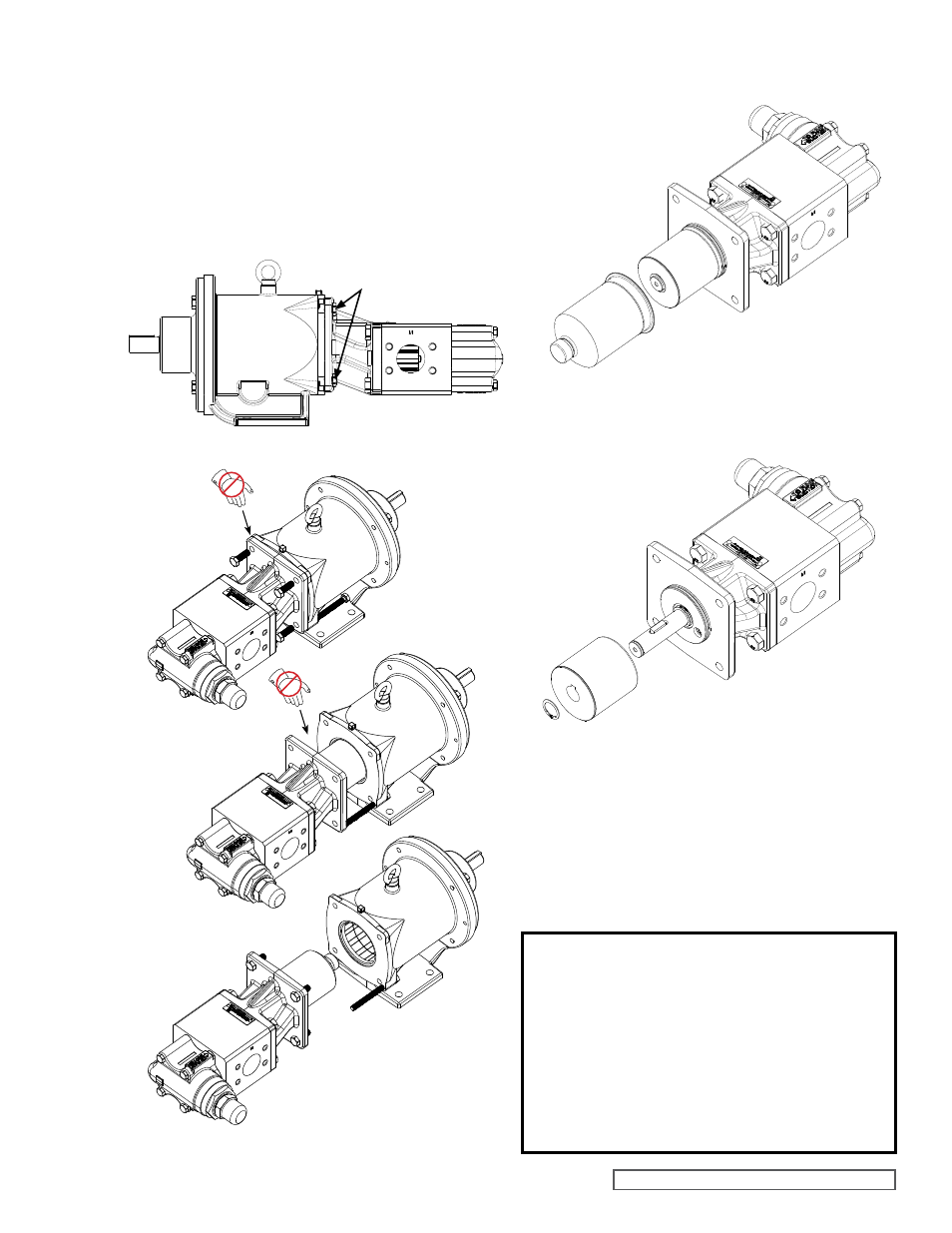
FIGURE 18
PUMP AND BRACKET SEPARATION SEQUENCE
MD2-B & MD2-C COUPLING
PUMP REMOVAL
Read all of the instructions before proceeding with
disassembly of the coupling and/or pump.
1. Remove the piping to the ports and remove the
capscrews securing the pump to the bracket. Support
the pump with an overhead hoist if possible. Use the M10
x 120 capscrew (jackscrew) in the bracket to separate
the inner magnet from the outer. (See
Figure 18).
CAUTION !
Use extreme caution, when pulling the inner
magnet away from the outer magnet (see
Figure 18). Do not place your fingers between
the pump mounting flange and the face of
the bracket. If you do not completely pull the
pump out it will snap back and could pinch
a finger or hand. Once the inner magnet is
removed from the bracket be careful setting it
down as it will attract any iron or steel object.
2. The canister will contain some liquid, therefore use care
while removing from the pump and pull it straight off. See
Figure 19.
FIGURE 17
3. Remove the external snap ring (closest to end of shaft)
and slide off the inner magnet assembly (See
Figure
20). Use caution, as this is a very strong magnet.
4. Do not remove the canister O-ring unless it is damaged,
especially if it is PTFE (Derivative) Encapsulated. If a
new O-ring is required, follow instructions in the
PUMP
ASSEMBLY section, page 12.
5. You should be able to visually inspect the outer magnets
from the end of the bracket. If removal is necessary,
start by removing the (4) capscrews and separating the
bracket from the motor or bearing carrier (See
Figure 12,
page 7). Loosen setscrews in outer magnet assembly to
pull assembly off shaft.
FIGURE 19
CANISTER REMOVAL
FIGURE 20
INNER MAGNET REMOVAL
BRACKET
CAPSCREWS (4)