Md-a & md-b coupling assembly, Danger, Caution – Viking Pump TSM341.1: SG Mag Drive Series User Manual
Page 10
SECTION TSM 341.1
ISSUE
J
PAGE 10 OF 19
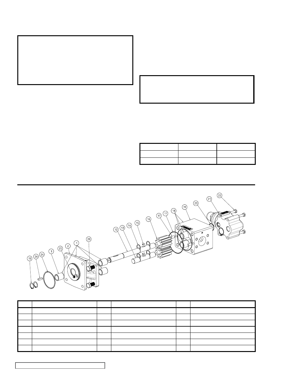
ITEM
NAME OF PART
ITEM
NAME OF PART
ITEM
NAME OF PART
1
Bracket & Bushing Assembly
14
Crescent Snap Rings (4 Required)
21
Relief Valve Assembly
2
Bracket
15
Gear Pins (2 Required)
22
Mounting Capscrews (4 Required)
3
Bushings (5 Required)
16
Gears (2 Required)
23
O-Ring for Relief Valve
10
External Retaining Rings (2 Required)
17
Alignment Pins (2 Required)
24
O-Ring for Canister
11
O-ring for Casing
18
Casing & Bushing Assembly
25
Orifice
12
Drive Shaft
19
Casing
26
Key for Inner Magnet
13
Driven Shaft
20
Capscrews (4 Required)
FIGURE 16
ExPLODED VIEW – MODELS SG-10 AND SG-14 MAG DRIVE PUMPS
TABLE 4
MD-A & MD-B COUPLING
ASSEMBLY
DANGER !
Follow these directions exactly to avoid injury
to self or damage to pumping unit. Be careful
to keep inner and outer magnets at least (1)
foot apart until step 4. Do not engage magnets
in any other fashion.
1. Inspect magnets for any metal objects that may be
attached. Remove any foreign material. Locate the outer
magnet assembly per drawing (See
Figure 13 on page
8). Apply Loctite to the set screw threads and tighten
both setscrews on to the motor or bearing carrier shaft.
The bearing carrier housing features a machined step
on its mounting flange, which is the reference point for
setting the position of the outer magnet.
2. Mount the bracket to the motor (or bearing carrier to
footed bracket) and secure with 4 capscrews (See
Figure 12 on page 7). Reach in and rotate magnets
by hand to make sure there is no interference. If
rubbing occurs, check the dimension. (See
Figure 13
on page 8).
3. Slide the inner magnet assembly onto the pump shaft
(with key and inner retaining ring in place) and secure
CAUTION !
Do not place fingers near mounting surface to
avoid pinching (See Figure 9 on page 7).
5. Finish assembly by securing the pump to the bracket.
With power disconnected, check to see if the pump turns
over freely. This may be done by spinning the motor fan
blades or bearing carrier shaft. Use specified torque
below:
FT-LBs:
Nm:
804
12-15
16-20
805
12-15
16-20
807
31-34
42-46
TABLE 1
with second retaining ring. Rotate the pump shaft and
magnet to make sure they turn freely. Inspect for any
foreign particles which could damage the pump. Check
the bracket O-ring to make sure it is in good condition
and installed properly. Place the canister onto the pump
and press on until the canister is in contact with the
pump bracket (See
Figure 11 on page 7).
4. Remove any foreign particles from the outside of the
canister, then slide the canister into the coupling bracket
(See
Figure 10 on page 7).