Viking Pump TSM141.1: G-LL 125/4125 User Manual
Page 9
SECTION TSM 141.1
ISSUE
E
PAGE 9 OF 16
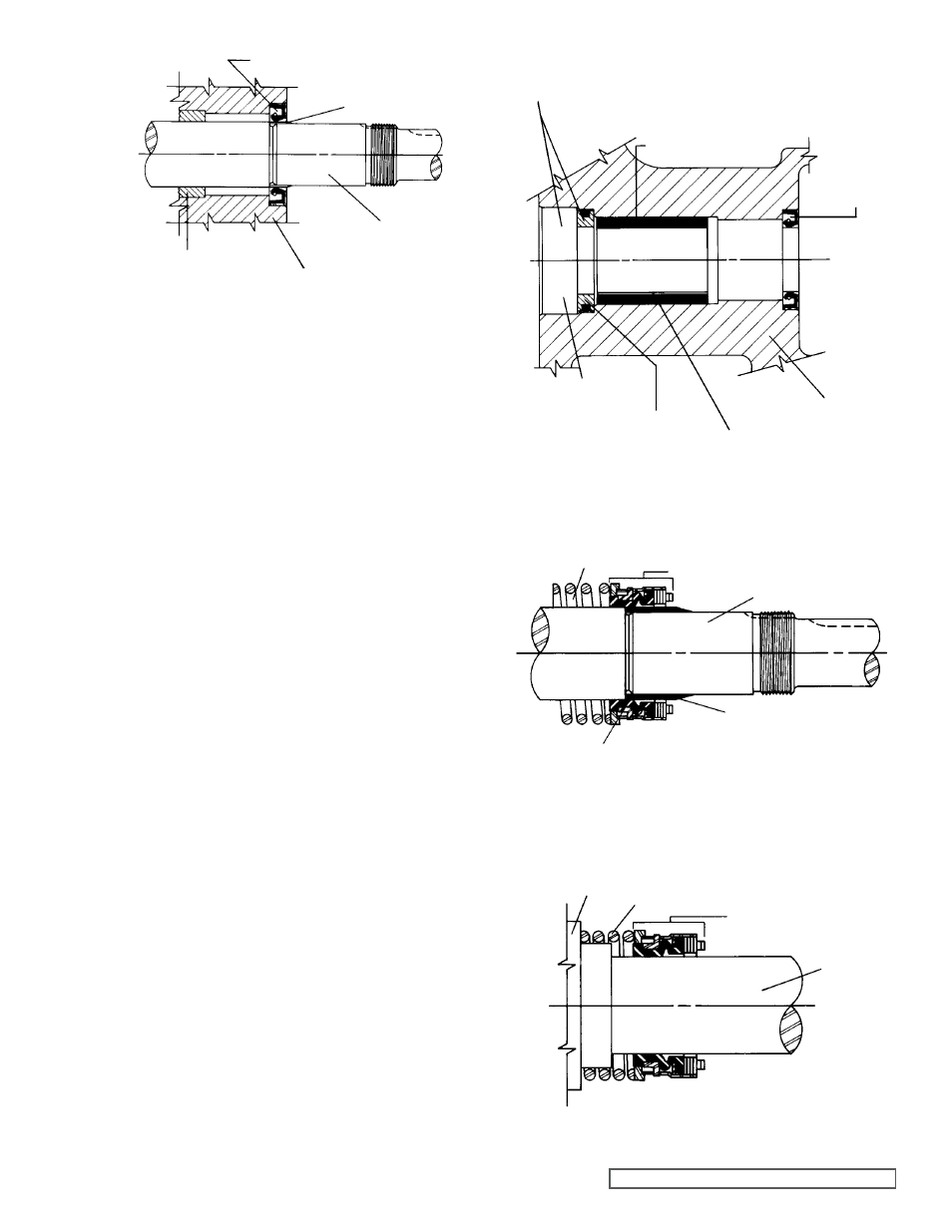
FIgURE 8
LIP SEAL FOR SEAL CHAMBER
TAPERED
INSTALLATION SLEEVE
BRACKET
BRACKET
BUSHINg
SHAFT
Prior to installing the rotating portion of the mechanical
seal, prepare and organize the rotor shaft, head and idler
assemblies and appropriate gaskets for quick assembly.
Once the rotating portion of the mechanical seal is installed
on the rotor shaft, it is necessary to assemble the parts as
quickly as possible to ensure that the seal does not adhere
to the shaft in the wrong axial position. The seal should
be expected to stick to the shaft after only a few minutes
setting time.
Never touch the sealing faces with anything except clean
hands or a clean cloth. Minute particles can scratch the seal
faces and cause leakage.
3. Coat
the idler pin with non-detergent SAE 30 weight oil
and place the idler and bushing on the idler pin in the
head. If replacing a carbon graphite bushing,
Refer to
Installation of Carbon graphite Bushings, page 14.
4. Clean the rotor hub and bracket seal housing bore.
Make sure both are free from dirt and grit. Coat the
outer diameter of the seal seat and the inner diameter
of the seal housing bore with non-detergent SAE 30
weight oil.
5. Start
the seal seat in the seal housing bore,
Refer to
Figure 9. If force is necessary, protect the seal face with
a clean cardboard disc and gently tap it in place with a
piece of wood.
6. Place
the tapered installation sleeve on the shaft,
Refer
to Figure 10. Sleeve is furnished with H, HL, K, KK, L,
LQ and LL size replacement mechanical seals. Coat the
rotor shaft, tapered installation sleeve and inner diameter
of the mechanical seal rotary member with a generous
amount of non-detergent SAE 30 weight oil. Petrolatum
may be used but grease is not recommended.
7. Place
the seal spring on the shaft against the rotor hub.
Refer to Figure 11.
8. Slide the rotary member, the lapped contact surface
facing away from the spring, over the installation sleeve
on the shaft until it is against the spring.
Do not compress the spring.
FIgURE 10
SPRINg
MECHANICAL SEAL ROTARY MEMBER
SHAFT
TAPERED
INSTALLATION SLEEVE
COAT ROTOR SHAFT, TAPERED INSTALLATION SLEEVE
AND INNER DIAMETER OF MECHANICAL SEAL WITH NON-
DETERgENT SAE 30 WEIgHT OIL BEFORE ASSEMBLY.
FIgURE 11
MECHANICAL SEAL
ROTARY MEMBER
SPRINg
SHAFT
ROTOR HUB
FIgURE 9
BRACKET
BUSHINg
LIP SEAL FOR
SEAL CHAMBER
BRACKET
BRACKET BUSHINg
LUBRICATION gROOVE
IN 12:00 O’CLOCK POSITION
SEAL SEAT
SEAL HOUSINg
BORE
COAT SEAL SEAT AND SEAL HOUSINg BORE
WITH NON-DETERgENT SAE 30 WEIgHT OIL
BEFORE ASSEMBLY.