Assembly, Danger – Viking Pump TSM141.1: G-LL 125/4125 User Manual
Page 10
SECTION TSM 141.1
ISSUE
E
PAGE 10 OF 16
9. Coat
the rotor shaft with non-detergent SAE 30 weight
oil. Start the end of the shaft in the bracket bushing and
turn from right to left, slowly pushing until the ends of the
rotor teeth are just below the face of the casing.
Leave the rotor in this position. Withdrawal of the rotor
and shaft may displace the carbon seal rotating face and
result in damage to the seal.
10. Using a .010 to .015 inch head gasket, install the head
and idler assembly on the pump. The pump head and
casing were marked before disassembly to ensure proper
reassembly. If not, be sure the idler pin, which is offset in
the pump head, is positioned toward and equal distance
between the port connections to allow for proper flow of
liquid through the pump.
If
the pump is equipped with a jacketed head plate, install
at this time along with a new gasket.
Tighten the head capscrews evenly.
Remove
the tapered installation sleeve from the shaft.
11. Slide the inner spacer collar over the shaft with the
recessed end facing the rotor. G, H and HL size bearing
spacer collars are not recessed.
Place the pair of half round rings on the shaft and slide
the inner bearing spacer collar over the half round rings
to lock them in place. There is no pair of half round
rings on G, H and HL size pumps.
Refer to Figure 6,
page 5.
12. Press the lip seal, lip facing the end of the shaft, in the
inner end cap and insert the end cap through the shaft
end of the bracket. Turn the end cap clockwise, looking
at the shaft end, until it engages the threads. End cap
spanner wrench holes must be facing the rotor. Turn the
end cap with a spanner wrench until it projects slightly
from opening on the side of the bracket. The end cap
must not be turned so far that the lip seal drops off
the end of the spacer collar on shaft or the end cap
becomes disengaged from the threads.
Refer to Figure
6, page 5.
If this happens, remove the inner spacer collar, half
round rings and end cap and start over at Step 11.
13. Pack the ball bearing with multi-purpose grease, NLGI
#2. Place on the shaft and push or gently drive into
place in the bracket.
14. Press the lip seal, lip facing the end of the shaft, in the
outer end cap and insert the end cap in the bracket.
Turn the end cap in the bracket until it is tight against the
bearing.
Refer to Figure 6, page 5.
15. Put the lockwasher and locknut on the shaft. Insert a
length of hardwood or brass through the port opening
between the rotor teeth to keep the shaft from turning.
Tighten the locknut and bend one tang of the lockwasher
into the slot of the locknut. There is no lockwasher on G
size pumps.
16. Adjust the pump end clearance. Refer to Thrust
Bearing Adjustment, page 14.
17. Lubricate the grease fitting over the seal chamber with
petroleum jelly, petrolatum (Vasoline) or other similar low
melting point lubricant. Lubricate all other grease fittings
with multi-purpose grease, NLGI #2.
DANgER !
Before starting pump, be sure all drive
equipment guards are in place.
Failure to properly mount guards may
result in serious injury or death.
ASSEMBLY
Optional Mechanical Seal
(PTFE Fitted Type)
The seal type shown in
Figures 12, 13 and 14 can be installed
as an alternate to the standard mechanical seal (synthetic
rubber bellows type). These seals are setscrew driven and
the stationary seats have anti-rotation pins which mate with
slots in the end of the bracket bushing.
1. Install the bracket bushing. If the bracket bushing has
a lubrication groove, install the bushing with the groove
at the 12:00 o’clock position in the bracket. If carbon
graphite,
Refer to Installation of Carbon graphite
Bushings, page 14.
2. Install
the lip seal in the bracket.
3. Clean the rotor hub and bracket seal housing bore. Refer
to Figure 12. Make sure both are free from dirt and grit.
Coat the outer diameter of the seal seat gasket and the
inner diameter of seal housing bore with non-detergent
SAE 30 weight oil.
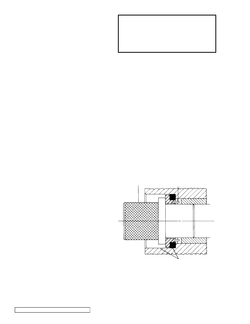
4. Start the seal seat in the seal housing bore. Make sure
the seat anti-rotation pins are aligned to engage the slots
in the end of the bracket bushing.
Refer to Figure 12.
FIgURE 12
INSTALLATION TOOL
ANTI-ROTATION PINS ALIgNED
WITH SLOTS IN BUSHINg
COAT WITH LIgHT OIL
BEFORE ASSEMBLY
BRACKET SEAL HOUSINg BORE WITH SEAL SEAT
INSTALLED. NOTE SPECIAL INSTALLATION TOOL USED
FOR FACTORY ASSEMBLY.