Viking Pump TSM141.1: G-LL 125/4125 User Manual
Page 11
SECTION TSM 141.1
ISSUE
E
PAGE 11 OF 16
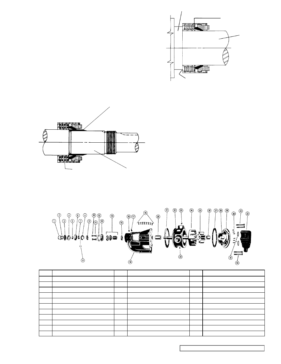
5. Using a cardboard disc to protect the lapped face of the
seal seat, press the seal seat assembly to the bottom of
the seal housing bore using a piece of wood. An arbor
press can also be used to install the seal seat. The seal
seat must be started square and carefully pressed to the
bottom of the seal housing bore.
K size pumps require a 0.25 inch spacer between the
seal and the rotor hub to properly position the seal on
the shaft.
6. Place
the tapered installation sleeve (furnished with H,
HL, K, KK, L, LQ and LL size replacement mechanical
seals) on the shaft.
Refer to Figure 13. Coat the inner
diameter of the seal rotary member, tapered installation
sleeve and the shaft with a generous quantity of non-
detergent SAE 30 weight oil. Place the rotary member
on the shaft over the sleeve and against the hub of
the rotor.
Refer to Figure 14.
Some PTFE seals are equipped with holding clips which
compress the seal springs. Remove the holding clips to
release the springs after the seal is installed on the shaft.
Tighten all drive setscrews securely to the shaft.
AT THIS POINT, FINISH ASSEMBLY PROCEDURES
STARTINg AT STEP 9, PAgE 10 (STANDARD
MECHANICAL SEAL).
FIgURE 13
FIgURE 14
TAPERED INSTALLATION SLEEVE
SHAFT
MECHANICAL SEAL
ROTARY MEMBER
ROTOR HUB
MECHANICAL SEAL
ROTARY MEMBER
SHAFT
0.25 INCH THICK SPACER COLLAR
USED HERE ON “K” SIZE PUMP.
EXPLODED VIEW OF MODELS AK4125 AND AL4125 (MODEL AK4125 SHOWN)
ITEM
NAME OF PART
ITEM
NAME OF PART
ITEM
NAME OF PART
1
Locknut
12
Seal Plate
23
Pipe Plug
2
Lockwasher (Not G)
13
Seal Holder
24
Rotor and Shaft Assembly
3
End Cap (Outer)
14
Mechanical Seal
25
Idler and Bushing Assembly
4
Lip Seal for End Cap
15
Set Collar with Setscrews
26
Idler Bushing
5
Bearing Spacer Collar (Outer)
16
Pipe Plug
27
Head Gasket
6
Ball Bearing
17
Grease Fitting
28
Idler Pin
7
Bearing Spacer Collar (Inner)
18
Bracket and Bushing Assembly
29
Head and Idler Pin Assembly
8
Ring, Half Round
19
Capscrews for Bracket
30
Capscrews for Head
9
End Cap (Inner)
20
Bracket Bushing
31
Relief Valve Gaskets
10
Seal Holder Nut
21
Bracket Gasket
32
Capscrews for Relief Valve
11
Seal Holder Capscrew
22
Casing
33
Internal Relief Valve