Danger – Viking Pump TSM141.1: G-LL 125/4125 User Manual
Page 13
SECTION TSM 141.1
ISSUE
E
PAGE 13 OF 16
8. Apply a generous amount of non-detergent SAE
30 weight oil to the large diameter of the shaft, the
tapered installation sleeve and the inner diameter of the
mechanical seal rubber parts.
9. Slide
the rotary member, lapped contact surface facing
away from the spring, over the installation sleeve on the
shaft until it is against the spring.
Do not compress the spring.
10. Lubricate the outer diameter of mechanical seal O-ring
seat gasket and flush the lapped seal faces with non-
detergent SAE 30 weight oil.
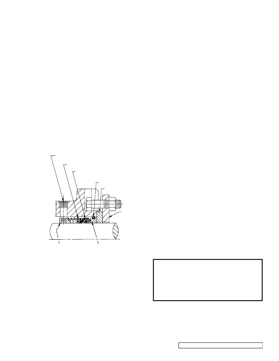
FIgURE 15
(LEFT SIDE OF PUMP)
ACCESS HOLE FOR TIgHTENINg
SETSCREWS IN SET COLLAR
SPRINg ADAPTER
MECHANICAL SEAL
(ROTARY MEMBER)
SEAL
HOLDER
PLATE
SEAL SEAT gASKET
SEAL HOLDER
SET COLLAR
SEAL SEAT
4. Using a .010 to .015 inch head gasket, install the head
and idler assembly on the pump. Pump head and casing
were marked before disassembly to ensure proper
reassembly. If not, be sure the idler pin, which is offset in
the pump head, is positioned toward and equal distance
between the port connections to allow for proper flow of
liquid through the pump.
If the pump is equipped with a jacketed head plate, install
at this time with a new gasket.
Tighten the head capscrews evenly.
5. Examine the set collar to be sure there are no burrs
or scratches and that the setscrews are withdrawn
so the shaft will not be scratched when the set collar
is installed.
6. Place the seal set collar on the shaft, push into the
seal chamber so the centerline of the setscrew coincides
with the centerline of the access hole on the left side of
the bracket (viewed from the shaft end).
Refer to Figure
15. Tighten the setscrews to secure the set collar to the
shaft.
7. Slide
the spring over the shaft into the seal chamber on
the set collar pilot. Place the tapered installation sleeve
on the shaft.
Refer to Figure 10, page 9.
11. Press the stationary seal seat in the bore until the
back, unlapped face, is just inside the bore. Position
the stationary seal seat by the installing seal holder
and secure the seal holder to the machined face of the
bracket with the seal holder plate.
12. Tighten the nuts securing the seal holder plate evenly so
the seal holder will not be distorted.
13. Remove the tapered installation sleeve.
14. Slide the inner bearing spacer collar over the shaft with
the recessed end facing the rotor.
Place the pair of half round rings on the shaft and slide
the inner bearing spacer collar over the half round rings
to lock them in place.
Refer to Figure 6, page 5.
15. Press the lip seal, lip facing the end of the shaft, in the
inner end cap and insert the end cap through the shaft
end of the bracket. Turn the end cap clockwise, looking
at the shaft end, until it engages the threads. End cap
spanner wrench holes must be facing the rotor. Turn the
end cap with a spanner wrench until it projects slightly
from the opening on the side of the bracket.
The end cap must not be turned so far that the lip seal
drops off the end of the spacer collar on the shaft or the
end cap becomes disengaged from the threads.
Refer
to Figure 6, page 5.
If this happens, remove the inner spacer collar, half
round rings and end cap and start over at Step 15.
16. Pack the ball bearing with multi-purpose grease, NLGI
#2. Place on the shaft and push or gently drive into place
in the bracket.
Install
the outer spacer collar.
17. Press the lip seal, lip facing the end of the shaft, in the
outer end cap and insert the end cap in the bracket. Turn
the end cap in bracket until it is tight against the bearing.
Refer to Figure 6, page 5.
18. Insert a length of hardwood or brass through the port
opening between the rotor teeth to keep the shaft from
turning. Put the lockwasher and locknut on the shaft,
tighten and bend the tang of the lockwasher into the slot
of the locknut.
19. Adjust the pump end clearance. Refer to Thrust
Bearing Adjustment, page 14.
20. Lubricate all grease fittings with multi-purpose grease,
NLGI #2.
DANgER !
Before starting pump, be sure all drive
equipment guards are in place.
Failure to properly mount guards may
result in serious injury or death.