2 connecting power, Connecting power, Figure 5. neutral - ground – line connections – Unitec C-Start Installation Manual User Manual
Page 12
C - S T A R T
Document Number: CST1001
8
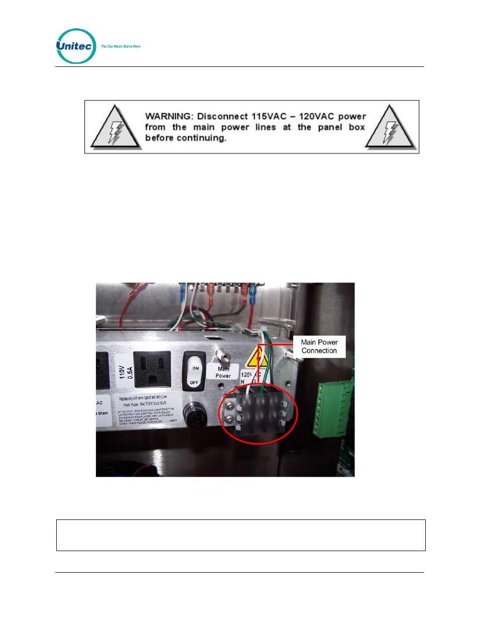
3.2 Connecting Power
1. Route the main power wires to the AC terminal strip on C-Start’s power panel
(as shown below) and trim the wire to remove excess. Strip the insulation
approximately ¼ ” on each conductor.
2. Remove the plastic shield on the power terminal block and loosen the 3
screws where the wires are to be connected. Install the Neutral (White),
Ground (Green), and Line (Black) wires under the screw clamps in the correct
positions (as shown below) and re-tighten the screws to hold the wires in
place.
3. Use wire ties to route and secure any extra cable. Replace the plastic shield.
Figure 5. Neutral - Ground – Line Connections
Warning!
For continued protection against risk of fire, replace only with the 8 amp/250V 3AG
SLO BLO fuse for C-Start.
Document Name: C-Start Installation Manual