Aluminum 50a n, Plasma / h, O shield – Tweco XT-300 Torch Data for Distributor UltraCut-100 AG User Manual
Page 19: This graphic is for reference only
Manual 0-4730 Rev. AG
8-19
TORCH DATA
(ga)
(in)
inch
(PSI)
Ball
(PSI)
Ball
(PSI)
Volts
(in)
±0.005
(ipm )
(in)
(s ec)
(in)
16
0.064
100
60
120
4
55
120
0.11
140
0.200
0.2
0.045
12
0.097
100
60
120
4
55
120
0.11
90
0.200
0.2
0.046
11
0.120
100
60
120
4
55
123
0.11
60
0.200
0.2
0.050
3/16
0.188
100
60
120
4
55
125
0.12
40
0.200
0.2
0.051
(Bar)
Ball
(Bar)
Ball
(Bar)
Volts
(m m )
±0.1
(mm/min)
(m m )
(s ec)
(m m )
6.9
60
8.3
4
3.8
120
2.8
2990
5.1
0.2
1.2
6.9
60
8.3
4
3.8
123
2.8
1520
5.1
0.2
1.3
6.9
60
8.3
4
3.8
124
2.9
1240
5.1
0.2
1.3
6.9
60
8.3
4
3.8
125
3.1
950
5.1
0.2
1.3
* Pres sure of the water s upply line s hould be regulated by cus tom er pres sure regulator.
Note1: Ohm ic height s ens ing is not recom m ended with water s hield. Water on the plate interferes electrically with the
ohm ic sensing circuit.
Note2: Water s ource us ed for s hield m us t be dem ineralized.
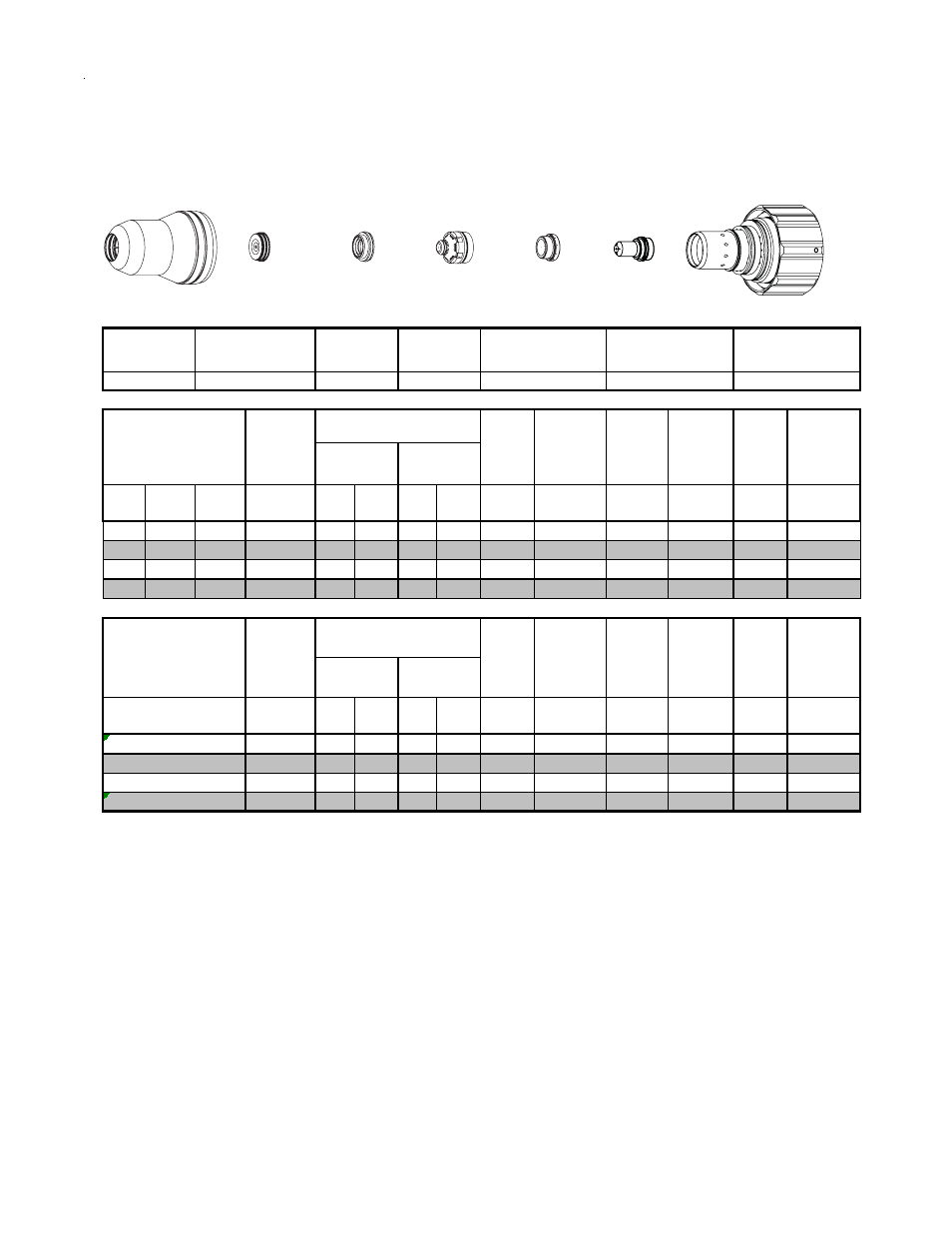
Aluminum
50A
N
2
Plasma / H
2
O Shield
Shield Cup
Shield Cap
Shield Gas
Distributor
Tip
Plasma Gas
Distributor
Electrode
Cartridge
21-1041
21-1078
21-1020
21-1016
21-1034
21-1274
21-1060
Material
Thicknes s
Pre Flow
Pres sure
(N
2
)
Cut Flow Rates /
Pres s ures
Arc
Voltage
Torch
Working
Height
Travel
Speed
Initial
Piercing
Height
Pierce
Delay
Kerf Width
@ Rec.
Speed
Plas m a
(N
2
)
Shield
(H
2
O)*
Material
Thicknes s
Pre Flow
Pres sure
(N
2
)
Cut Flow Rates /
Pres s ures
Arc
Voltage
Torch
Working
Height
Travel
Speed
Initial
Piercing
Height
Pierce
Delay
Kerf Width
@ Rec.
Speed
Plas m a
(N
2
)
Shield
(H
2
O)*
Requires CCM version 3.4 or later. Requires GCM vers ion 3.2 or later
4
3
(m m )
2
5
BOLD TYPE indicates m axim um piercing param eters.
Shield
Gas Distributor
Electrode
Tip
Shield Cap
Shield Cup
This Graphic Is For Reference ONLY
Plasma Gas
Distributor
Art # A-08418
Cartridge