03 basic troubleshooting – Tweco CE Ultima 150 User Manual
Page 31
Manual 0-2530
25
SECTION 5: GENERAL MAINTENANCE
2. Flushing the System
As part of general maintenance, periodically the
cooling system should be flushed. To flush the sys-
tem, remove the hose fitting at the filter end of the
Coolant Filter Assembly and drain into an appro-
priate container. Do not turn on the pump. Grav-
ity flow will drain the Reservoir.
3. Coolant Conductivity
The coolant conductivity LED on the front panel
must be green for normal operation. If the LED is
red then flush the old coolant from the system.
To flush the cooling system, remove the hose fitting
at the filter end of the Coolant Filter Assembly and
drain into an appropriate container. Do not turn
on the pump. Gravity flow will drain the Reser-
voir. Refill cooling system with Thermal Arc
®
Torch
Coolant.
CAUTIONS
Handle and dispose of the used coolant per recom-
mended procedures.
Do Not turn on the pump. Running the cooling
pump dry will cause premature failure of the pump.
Pump pressure is preset at the factory and should
not require attention.
5.03 Basic Troubleshooting
This manual covers basic troubleshooting that requires
limited disassembly and measurements. Most common
problems can be resolved with the information provided
in this section.
For major troubleshooting for this product, see the UL-
TIMA-150 Service Manual No. 0-2503.
NOTE
If major complex assemblies are faulty, the unit must
be returned to an authorized service center for re-
pair.
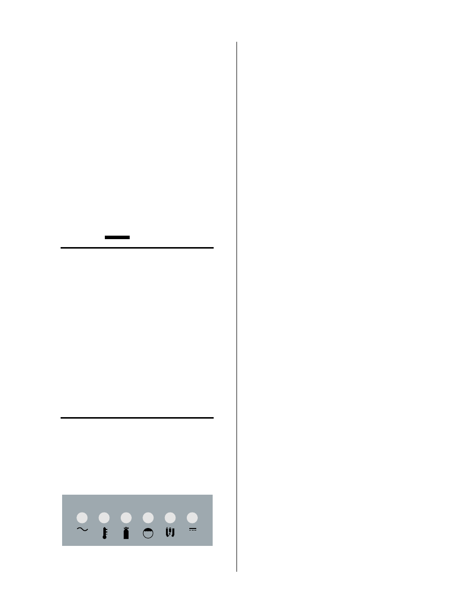
The ULTIMA-150 Power Supply provides Status Indica-
tor Lights to indicate potential source of most problems.
Check here to identify the nature of a problem.
COOL
PILOT
DC
GAS
TEMP
AC
A-00823
Figure 5-3 Front Panel Status Indicator Lights
A. AC Power Problems
1. AC light indicator not on; fan does not operate
a. Switch at customer's main power panel in OFF position
• Close main power panel switch
b. Input power fuse (F1) blown or loose
• If blown, double-check input voltage against
voltage selection inside unit. Replace input
power fuse (Refer to Section 5.04, Basic Parts
Replacement)
c. Incorrect voltage applied
• Check input line for correct voltage
d. Customer's main power fuse(s) blown or loose
• Check main power fuse(s) and replace as re-
quired
e. Input power not properly connected to customer's main
power panel
• Check that input power is present and unit is
properly connected (refer to Section 3.04, Pri-
mary Input Power Connections.
f. Defective input power cable
• Check cable and replace if faulty
2. AC light is on; fan operates slow
a. Incorrect voltage selection
• Check High-Low Voltage Selection. Must be re-
placed by a Thermal Dynamics EMI Suppres-
sion Cable.
B. Temperature Problems
1. Temp light is RED
Overtemperature of the power supply or coolant will
immediately disable the power supply output. The
recirculator pump remains running to cool down the
system and coolant
a. Obstructed air flow outside power supply
• Check to insure there is adequate space around
power supply. See Section 3.02, Site Location,
for more information
b. Exceeded duty cycle
• Exceeded duty cycle causing power supply or
coolant to overheat. Refer to Section 2.03, Speci-
fications, for correct Amps and Duty Cycle