Appendix b - automation – Tweco 185TSW DC CC User Manual
Page 58
58
APPENDIX B - AUTOMATION
JUMPER SETTING FOR "OK–TO–MOVE". Models 185TSW
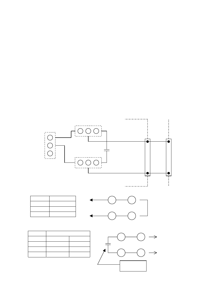
Three jumpers (JP1, JP2 and JP3) are provided on PC Board WK-4921 for automation purposes. This
PCB is mounted horizontally on top of the unit just under the cover. This PCB can be accessed by
removing the side covers by loosening 4 screws on each the front and rear panel, then removing the 4
side panel screws as well as the 2 handle screws. Carefully pull the front and rear panels outward to
release and remove the side cover. Remove two plastic clips holding the PCB protective cover in place
and lift the sheet up and over the unit. The jumpers will be accessible on the top portion of the PCB.
See figure on next page for the location of the PCB.
All units are shipped from the factory with the jumpers set in position "A". This is for normal semi-
automatic operation utilizing a remote device, such as a foot control. The 8-pin remote operates as
described earlier in this manual.
Placing all jumpers in position "B" would be primarily used for automation with an arc establish relay,
remote amperage and contactor. An arc-establish signal is located from pins 4 and 8 when in this mode.
Placing jumpers JP1 and JP2 in "B" position and jumper JP3 in "A" position would have the
configuration of an arc-establish signal and remote contactor, but the unit’s front panel would control
the amperage.
•
Set All "A" position : factory shipping
POSITION
JP1
A
JP2
A
JP3
A
•
Use "OK TO MOVE signal"
POSITION
JP1
B
B
JP2
B
B
JP3
B
A
A/V
REMOTE
PANEL
JP1
A COM B
JP2
A COM B
B
COM
A
OK-TO-MOVE
RELAY
WK-4921
CN6
CON1
4 4
8 8
JP3
8
4
4
CN6 CON1
8
Remote : Short 4 to 8
Panel : Open
8
4
4
CN6 CON1
8
OK TO MOVE
RELAY
Max Load:
24V 50ma.