Cutmaster a60 – Tweco A60 Cutmaster User Manual
Page 24
CUTMASTER A60
INSTALLATION
Manual 0-4981
3-2
Most units are shipped from the factory with a 230 Volt input
power cable wired to the input contactor in the single - phase
configuration. The following illustrations and directions are
for changing that configuration to a different voltage and or to
three - phase operation or back again if a change had already
been made.
A. Cover Removal
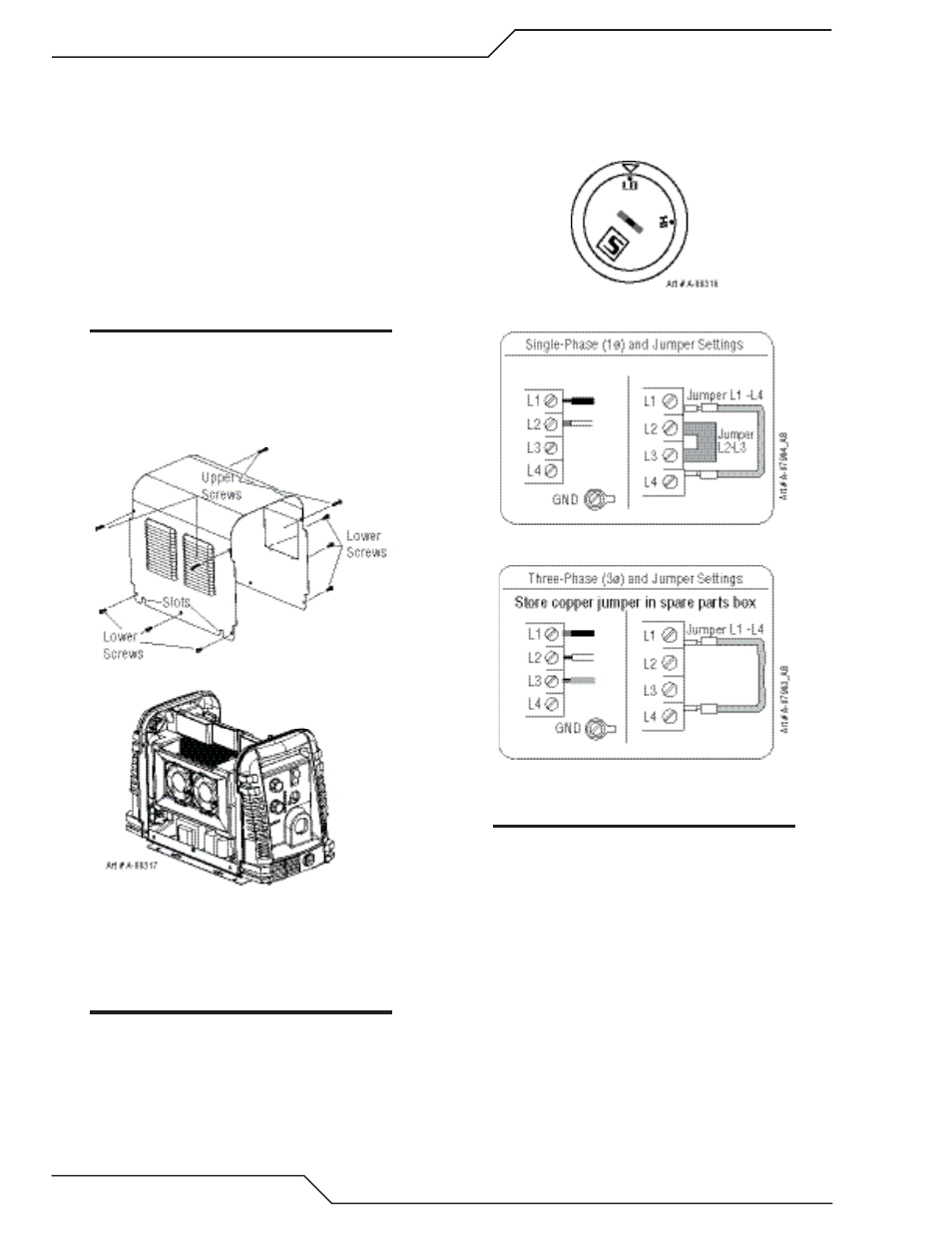
1. Remove the upper and lower screws which secure the
cover to the main assembly. Do not loosen the lower
screws inside the cut out slots in the bottom of the
cover.
NOTE
The upper screws and lower screws are not the
same. Do not mix them. The upper screws are
for threading into the plastic of the front and rear
panels. DO NOT use the finer threaded lower
screws for this.
2. Carefully pull the Cover up and away from the unit.
B. Cover Installation
1. Reverse previous procedures for cover installation.
NOTE
When installing the upper screws, attempt to reuse
the original threads. The easiest way to do this is
by turning the screw counter-clockwise until you
feel the threads line up, then begin to turn the screw
clockwise to tighten. Do not over tighten.
C. Input Power Selection
Set the Input Voltage Selection Switch at the rear of the unit
based on the primary input voltage it is connected to. Low is
208/230 VAC and high is 460 VAC.
D. Quick Guide to Phase Wiring
Single Phase Input Power Wiring
Three Phase Input Power Wiring
NOTE
There is only one jumper setting that changes
between the single and three phase settings. To
change from single phase to three phase, the cop-
per bus bar jumper connected to L2 and L3 needs
to be removed and placed in a safe place for re-
use. We suggest the spare parts box in the power
supply. See previous illustrations.