Cutmaster 40mm, 04 gas connections – Tweco 40mm Cutmaster User Manual
Page 24
CUTMASTER 40mm
INSTALLATION 3-2
Manual 0-5084
5. Pass the cable being used through the
access opening in the back panel of the
power supply. Refer to Section 2 for
power cable specifications.
CAUTION
The primary power source and power cable must
conform to local electrical code and the recom-
mended circuit protection and wiring require-
ments (refer to table in Section 2).
6. Connect the wires as follows.
• Wires to L1, L2 and L3 input. It does
not matter what order these wires are at-
tached. See previous illustration and on
label in the power supply.
• Green / Yellow wire to Ground.
7. With a little slack in the wires, tighten
the through - hole protector to secure the
power cable.
8. Reinstall the Power Supply cover per in-
structions found in section 5.
9. Connect the opposite end of individual
wires to a customer supplied plug or main
disconnect.
10. Connect the input power cable (or close
the main disconnect switch) to supply
power.
3.04 Gas Connections
Connecting Gas Supply to Unit
The connection is the same for compressed air or
high pressure cylinders. Refer to the following
two subsections if an optional air line filter is to
be installed.
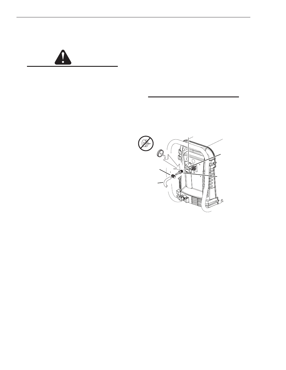
1. Connect the air line to the inlet port. The
illustration shows typical fittings as an
example.
NOTE
For a secure seal, apply thread sealant to the
fitting threads, according to manufacturer's
instructions. Do not use Teflon tape as a thread
sealer, as small particles of the tape may break
off and block the small air passages in the torch.
Art # A-07943
Hose Clamp
Regulator/Filter
Assembly
Inlet Port
Gas Supply
Hose
1/4 NPT or ISO-R
to 1/4” (6mm) Fitting
Air Connection to Inlet Port