D. optional high-flow water shield cable, E. optional gas control connection – Tweco Merlin 6000 Master PS User Manual
Page 33
Manual 0-2568
3-15
INSTALLATION PROCEDURES
• Standoff Control SC10 used with the Remote
Control RC6010
Connect the internal ribbon cable to the Remote
Control RC6010. Refer to the Standoff Control In-
struction Manual for more details.
• Standoff SC11 only
The standoff control remote cable connects to the
receptacle marked REMOTE CONTROL (J15) on
the rear panel of the Power Supply.
A-01506
Cable From
Standoff Control
REMOTE CONTROL
Connector (J15)
OUTP
UT
OUTPUT
TO
TO
CON
TROL
CONTROL
MOD
ULE
MODULE
AIR
AIR
PLAS
MA
PLASMA
INPUT
INPUT
N
2
PLAS
MA
PLASMA
INPU
T
INPUT
O
2
PLAS
MA
PLASMA
INPU
T
INPUT
PLAS
MA G
AS
PLASMA GAS
Ar/H
Ar/H
2
PLAS
MA
PLASMA
INPU
T
INPUT
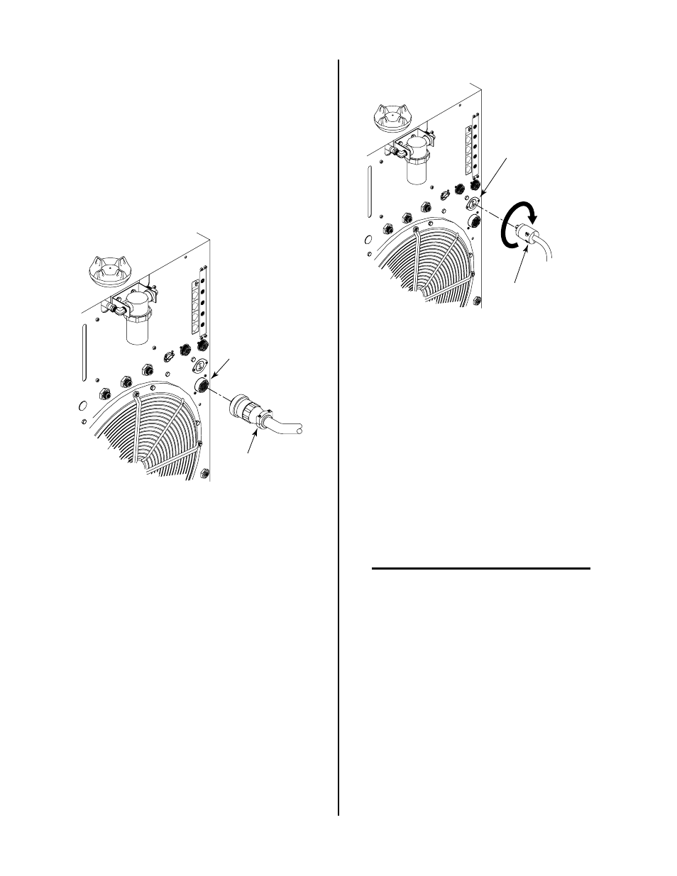
Figure 3-22 Standoff Control Interface Connection
D. Optional High-Flow Water Shield Cable
The High Flow Water Shield surrounds the main cutting
arc with a spray of water to reduce arc glare, noise, and
fumes. Use of the water shield device reduces the
system’s overall cutting capacity. Refer to the High-Flow
Water Shield Instruction Manual for more information.
1. Connect the high flow water shield interface cable
to the receptacle marked HIGH FLOW WATER
SHIELD on the rear panel of the Power Supply.
The receptacle is 115VAC.
High Flow Water Shield
Interface Cable
High Flow Water Shield
Connector (J63)
Rotate Clockwise
To Lock
A-01507
OUTP
UT
OUTPUT
TO
TO
CON
TROL
CONTROL
MODULE
MODULE
AIR
AIR
PLASMA
PLASMA
INPUT
INPUT
N2
PLASMA
PLASMA
INPUT
INPUT
O2
PLASMA
PLASMA
INPUT
INPUT
PLAS
MA G
AS
PLASMA GAS
Ar/H
Ar/H
2
PLASMA
PLASMA
INPUT
INPUT
Figure 3-23 High Flow Water Shield Interface
Connection
2. Rotate the plug clockwise to lock the plug to the
receptacle.
3. To shut off the high flow water shield remove the
interface cable or disconnect power to the High
Flow Water Shield (HFWS) accessory.
E. Optional Gas Control Connection
The optional GS3000 Gas Control allows the connection
of various multiple plasma and secondary gases to be
connected to the Power Supply. The proper plasma and
secondary gas is selected with switches on the front panel
of the Gas Control Option.
NOTE
The secondary selection switch on the front panel
of the Power Supply must always be set to GAS
for all secondary gases when the Gas Control Op-
tion is installed.
1. Connect the Gas Control control cable to the con-
nector marked GAS CONTROL (J63) on the rear
panel of the Power Supply.