06 servicing machine torch components, 06 servicing machine torch components -6 – Tweco Maximizer 300 Torch for BNFL User Manual
Page 36
SERVICE
5-6
Manual 0-2990
5.06 Servicing Machine Torch
Components
WARNINGS
Disconnect primary power to the system before
disassembling the torch or torch leads.
DO NOT touch any internal torch parts while the
AC indicator light on the front panel of the Power
Supply is ON.
A. Removing Machine Torch Head
1. Remove the shield cup, tip, gas distributor and
electrode from the torch head assembly.
2. Unscrew the positioning tube from the torch
adapter on the torch head assembly and slide the
positioning tube up the leads.
A-01998
Figure 5-5 Torch Mounting Assembly
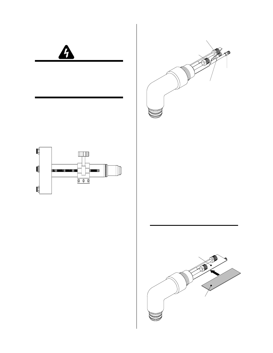
3. Disconnect the plasma, secondary (+), coolant
supply and coolant return (-) fitting connections.
Note the location of the torch leads insulator
which separates the negative and positive leads.
Plasma Lead
Coolant Return (-) Lead
(LH Threads)
Secondary (+)
Lead
Coolant
Supply Lead
A-01989
Figure 5-6 Torch Head Removal
4. Remove the rigid insulator from the old Torch
Head Assembly from between the layers of
estermate paper.
5. Unscrew and remove the torch adapter from the
torch head assembly.
B. Reassembling Machine Torch Assembly
1. Slide the torch adapter down over the leads and
screw the adapter securely onto the back of the
torch head assembly.
2. Slide the rigid insulator between the layers of
estermate paper on the replacement Torch Head
Assembly (see note).
NOTE
Over a period of time there may be a breakdown of
the estermate paper causing the Torch Head to short
out if the rigid insulator is not installed.
Two Layers Of
Estermat Paper
Rigid Torch
Leads Insulator
A-01990
Figure 5-7 Rigid Insulator Installation