Cutmaster 10mm, 12mm, 2t.03 introduction to plasma – Tweco CutMaster 10mm-12mm User Manual
Page 20
CUTMASTER 10MM, 12MM
TORCH INTRODUCTION 2T-2 Manual 0-5197AC
2T.03 Introduction to Plasma
A. Plasma Gas Flow
Plasma is a gas which has been heated to an extreme-
ly high temperature and ionized so that it becomes
electrically conductive. The plasma arc cutting and
gouging processes use this plasma to transfer an
electrical arc to the workpiece. The metal to be cut
or removed is melted by the heat of the arc and then
blown away.
While the goal of plasma arc cutting is separation of
the material, plasma arc gouging is used to remove
metals to a controlled depth and width.
In a Plasma Cutting Torch a cool gas enters Zone B,
where a arc between the electrode and the torch tip
heats and ionizes the gas. The main cutting arc then
transfers to the workpiece through the column of
plasma gas in Zone C.
By forcing the plasma gas and electric arc through a
small orifi ce, the torch delivers a high concentration
of heat to a small area. The stiff, constricted plasma
arc is shown in Zone C. Direct current (DC) straight
polarity is used for plasma cutting, as shown in the
illustration.
Zone A channels a secondary gas that cools the torch.
This gas also assists the high velocity plasma gas in
blowing the molten metal out of the cut allowing for
a fast, slag-free cut.
;;
;;
;;
;
;
;
;
;
;;
;;
A-00002
Workpiece
Power
Supply
+
_
C
B
A
Figure 2T-2 - Typical Torch Head Detail
B. Gas
Distribution
The single gas used is internally split into plasma and
secondary gases.
The plasma gas fl ows into the torch through the
negative lead, through the starter cartridge, around
the electrode, and out through the tip orifi ce.
The secondary gas fl ows down around the outside
of the torch starter cartridge, and out between the tip
and shield cup around the plasma arc.
C. Pilot
Arc
When the torch is started a pilot arc is established
between the electrode and cutting tip. This pilot
arc creates a path for the main arc to transfer to the
work.
D. Main Cutting Arc
DC power is also used for the main cutting arc. The
negative output is connected to the torch electrode
through the torch lead. The positive output is con-
nected to the workpiece via the work cable and to the
torch through a pilot wire.
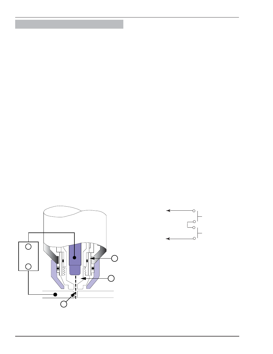
E. Parts-in-Place
(PIP)
The torch includes a 'Parts-in-Place' (PIP) circuit.
When the shield cup is properly installed, it closes
a switch. The torch will not operate if this switch is
open.
Torch Trigger
PIP Switch
Shield Cup
To Control
Cable Wiring
Torch Switch
A-09595
Figure 2T-3 - Parts-in-Place Circuit Diagram for Hand Torch