Tweco 6000 Cutting System User Manual
Page 18
INSTALLATION PROCEDURES
14
Manual 0-2572
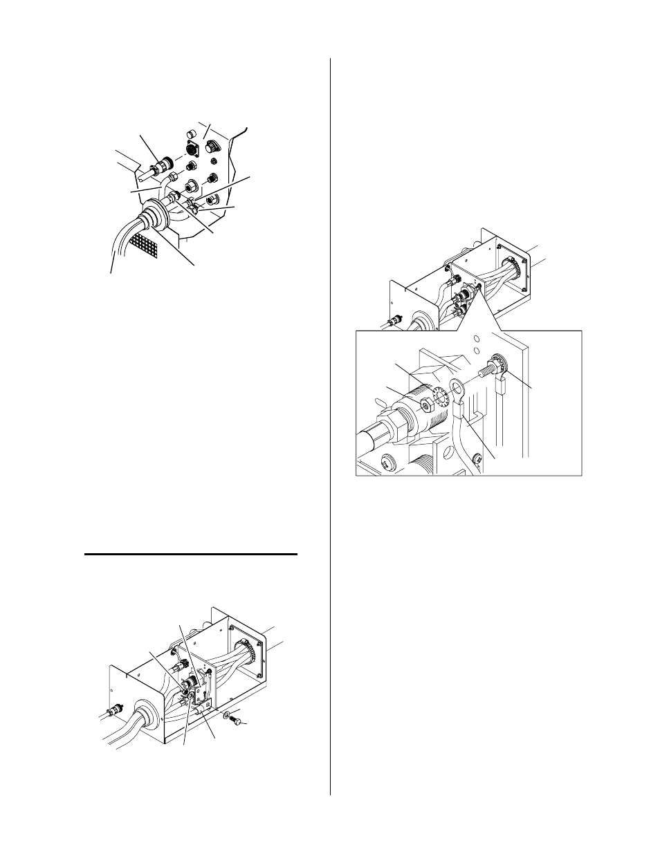
5. Connect the other end of the Torch Supply Leads
fittings onto the mating connections at the input
panel of the Master Plasma Power Supply.
Secondary
Gas Lead
Torch Supply Leads
Supply Leads Boot
Coolant Return
Lead
Coolant Supply
Lead
Plasma
Gas Lead
A-01447
Control Cable
Master Power Supply
Bulkhead
Figure 3-9 Torch Supply Leads Connection To
Master Power Supply
6. Feed the power lead through the boot and con-
nect to the buss bar per the following procedure:
a. Remove the nut and washer from the lower
bolt.
b. Remove the bolt and washer from the lower
hole of the buss bar.
c. Place the ring lug on the power lead over the
end of the bolt.
d. Re-install the bolt and washer with the lug
into the lower hole of the buss bar.
e. Re-install the nut and washer to secure the
lead.
NOTE
Installing the power lead on the lower bolt will
make it easier to install the second power lead if a
dual system is to be used.
A-01974
Buss Bar
Washer
Bolt
Power Lead
Nut
Washer
Figure 3-10 Power Lead Connection
7. Feed the pilot lead through the boot and connect
to the pilot connection per the following proce-
dure:
a. Remove the nut and external star washer from
the pilot connection bolt.
b. Place the ring lug on the pilot wire over the
end of the bolt.
c. Re-install the external star washer and nut to
secure the lead.
Star
Washer
Nut
Pilot Lead
Pilot Lead
Connection
A-01975
Figure 3-11 Pilot Lead Connection
8. Connect the other end of the Pilot Lead, two wires,
to the Master Power Supply per the following pro-
cedure:
a. Remove the right side panel from the Master
Power Supply.
b. Feed the Pilot Lead, two wires, through the
small strain relief at the front panel of the Mas-
ter Power Supply.
c. Remove the nut and star washer on the ground
terminal of the pilot connection inside the
power supply.