Section 3: installation procedures, 01 introduction, 02 site location – Tweco 6000 Cutting System User Manual
Page 15: 03 unpacking, 04 mounting arc starter box, Section 3, Installation procedures
Manual 0-2572
11
INSTALLATION PROCEDURES
SECTION 3:
INSTALLATION
PROCEDURES
3.01 Introduction
This Section describes installation of the Arc Starter Box.
These instructions apply to the Arc Starter Box Assem-
bly only; installation procedures for the Plasma Power
Supply, Torch and Torch Leads, Options, and Accesso-
ries are given in Manuals specifically provided for those
units.
The complete installation consists of:
1. Site Selection
2. Unpacking
3. Mounting Arc Starter Box
4. Connecting Torch and Supply Leads
5. Operator Training
3.02 Site Location
Select a clean, dry location with good ventilation and
adequate working space around all components.
Review the safety precautions in the front of this manual
to be sure that the location meets all safety requirements.
3.03 Unpacking
Each component of the system is packaged separately
and protected with a carton and packing material to pre-
vent damage during shipping.
A. Unpacking Procedure
1. Unpack each item and remove all packing mate-
rial.
2. Locate the packing list(s) and use the list to iden-
tify and account for each item.
3. Inspect each item for possible shipping damage.
If damage is evident, contact your distributor
and/or shipping company before proceeding with
system installation.
3.04 Mounting Arc Starter Box
Mount the Arc Starter Box to the cutting table gantry
per the following procedure:
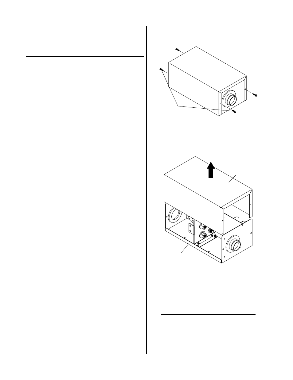
1. Remove the four screws securing the cover to the
base assembly of the Arc Starter Box.
Screws
(Four Places)
A-01436
Figure 3-1 Cover Screw Removal
2. Slide the cover up and off the base assembly.
Base Assembly
A-01969
Cover
Figure 3-2 Cover Removal
3. Mount the base assembly of the Arc Starter Box to the
cutting table gantry using the four holes provided in
the base.
NOTE
The last page of this Manual has a full size hole
template for use in locating the mounting holes.