3 optional leak sensing – Trebor 55E EVOLVE User Manual
Page 8
PAGE 8
EVOLVE 55E PUMP OPERATION / MAINTENANCE MANUAL
Figure 2-2: Generic Connection Diagram
NOTE: See Surge Suppressor Operation Manual for detailed installation instructions.
2.3 OPTIONAL LEAK SENSING
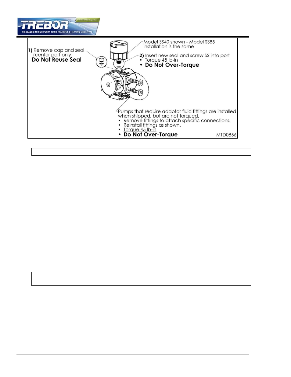
2.3.a Installation
Remove plug and seal from port. Probe is self-sealing.
Install probe assembly into leak sensor port.
Thread probe cap into port. (NOTE: Do not over tighten; damage to threads will occur.)
Push protective tubing into probe cap.
Connect fiber optic cable to sensor (NOTE: Minimize bends in fiber optic cable to 2”
radius minimum to help ensure optimum signal strength.) Fiber optic cable can be cut to
desired length using the cable cutter provided.
2.3.b Sensor Signal Specifications
The sensor signal is normally closed. In the event of a leak, no light signal is returned to
the sensor.
NOTE: See your fiber optic sensor installation instructions for proper connection and
adjustment.