Installation, Step four, Step one – tekmar 650 Snow Melting Control User Manual
Page 2: Step two, Step three
©
2010 D
650
-
08/10
2
of
4
Step Four
Testing and connecting the wiring
Caution
These tests are to be performed using standard testing practices and procedures and should only be carried out by properly
trained and experienced persons. A good quality electrical test meter, capable of reading from at least 0 — 200 Volts, and
at least 0 — 2,000,000 Ohms, is essential to properly test this control. At no time should voltages in excess of 28 V be
measured at any of the wires connected to the control.
Test the sensors
• This test must be performed
before power is applied to the control and before the sensors are connected to the terminal strip.
Test the sensors according to the instructions printed in the enclosed Data Brochure D 072.
Test the power supply
• Ensure exposed wires are not grounded or in contact with other wires. Turn on the 24 V ac power supply and, using a
voltmeter, you should measure between 20 and 28 volts between the power and common terminals.
• Turn off the power and complete the electrical connections to the terminal strip of the control.
Power and output connections
The installer should test to confirm that no voltage is present at any of the wires.
• Connect the power supply to terminals
Power C — R (1 and 2).
• Connect the heating device circuit to terminals
Heat (3 and 4).
• Connect the system circuit to terminals
System (5 and 6).
Sensor connections — Caution, voltage is never applied to these terminals
• Connect the Slab Sensor 072 to terminals
Com Sen and Slab Sen (7 and 8).
• Connect the Outdoor Sensor 070 to terminals
Com Sen and Out Sen (7 and 9).
Caution
Improper installation and operation of this control could result in damage to the equipment and possibly even
personal injury. It is your responsibility to ensure that this control is safely installed according to all applicable codes
and standards. This electronic control is not intended for use as a primary limit control. Other controls that are
intended and certified as safety limits must be placed into the control circuit.
Step One
Getting ready
Check the contents of this package. If any of the contents listed are missing or damaged, please refer to the Limited Warranty
and Product Return Procedure on the back of this brochure and contact your wholesaler or tekmar sales agent for assistance.
Type 650 includes:
• One Snow Melting Control 650 • One Slab Sensor 072 • One Outdoor Sensor 070
• Data Brochures D 001, D 070, D 072, D 650 • Application Brochures A 650
Other information available:
• Essay E 001, Essay E 005.
Note: Carefully read the Sequence of Operation section in this brochure to ensure that you have chosen the proper control and
understand its functions within the operational requirements of your system.
Step Two
Mounting
The control is mounted in accordance with the instructions in the Data Brochure D 001.
Step Three
Rough-in wiring
All electrical wiring terminates in the two wiring chambers at the bottom front of the control. If the control is to be mounted on
an electrical box, the wiring can be roughed-in at the electrical box prior to installation of the control (see Brochure D 001).
Standard 18 AWG solid wire is recommended for all low voltage wiring to this control.
Installation
• Install the Outdoor Sensor 070 according to the instructions in Data Brochure D 070 and run the wiring back to the control.
Do not connect the wires to the terminals yet.
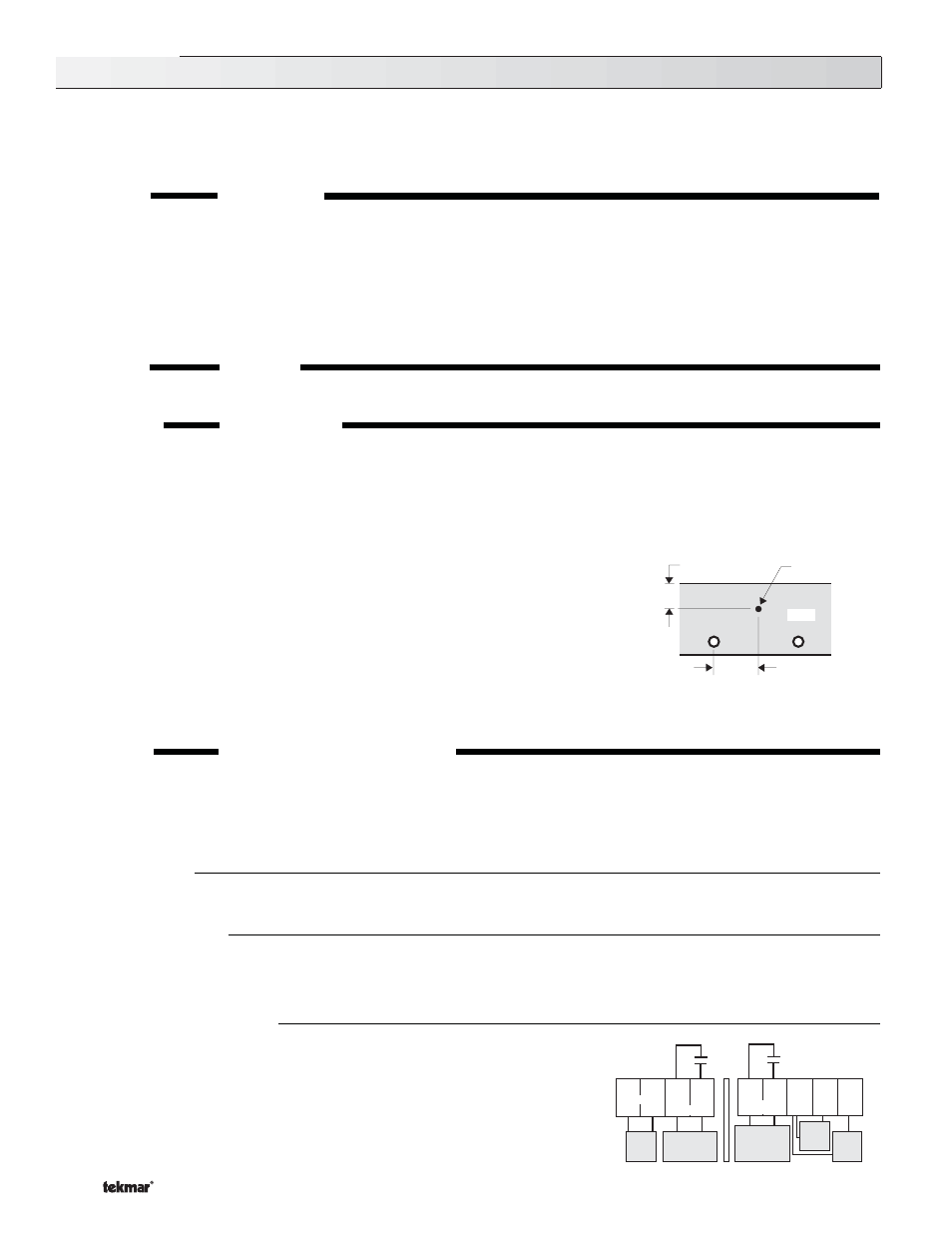
• Install the Slab Sensor 072 in the slab halfway between the heating pipes or electric
cables and within 1 inch of the slab surface (see adjacent diagram). The sensor
should be placed approximately 3 feet (1m) from the edge of the slab. Run the wiring
back to the control but do not connect the wires to the terminals yet.
• Install a 24 V (ac) Class 2 transformer with a minimum 5VA rating and run the wiring
from the transformer to the control.
A Class 2 transformer must be used. Do not
connect either of the transformer secondary wires to ground.
• Or provide a 24V DC power source and run wiring to the control location.
1" (25mm)
halfway between the
pipes or electric cables
Slab Sensor
SLAB
Power should not be applied to any of the wires during the rough-in wiring stage.
24 V Only
Do not apply
power here
24 V
power
supply
Heat Relay
closes to turn on
heating device
System Relay
closes when in
melting or idling
modes
1
C-
2
R+
3
4
10A
10A
Heat
System
5
6
Slab
Sen
Out
Sen
8
9
Slab
Sensor
072
Outdoor
Sensor
070
Power
7
Com
Sen
Data Brochures:
• Run wiring from the heating device and system circuits to the control.