tekmar 519 Thermostat Installation User Manual
Page 7
© 2013
519_D - 03/13
7 of 16
A Watts Water Technologies Company
Slab Sensor 079 Testing
A good quality test meter capable of measuring up to 5,000 kΩ (1 kΩ = 1000Ω) is
required to measure the sensor resistance. In addition to this, the actual temperature
must be measured with either a good quality digital thermometer, or if a thermometer
is not available, a second sensor can be placed alongside the one to be tested and
the readings compared.
First measure the room temperature using the thermometer. Disconnect the Sen and
Com wires from the thermostat. Using an electrical meter, measure the resistance of the
Sen and Com wires at the thermostat location. Using the temperature versus resistance
table, estimate the temperature measured by the sensor. The sensor measurement and
thermometer readings should be close. If the test meter reads a very high resistance,
there may be a broken wire, a poor wiring connection or a defective sensor. If the
resistance is very low, the wiring may be shorted, there may be moisture in the sensor
or the sensor may be defective. To test for a defective sensor, measure the resistance
directly at the sensor location. Once the test has been completed, reconnect the Sen
and Com wires to the thermostat.
Do not apply voltage to the temperature sensor terminals at any time as damage to
the sensor may result.
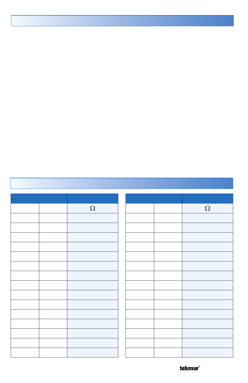
Temperature vs. Resistance Table
Temperature
Resistance
°F
°C
-50
-46
490,813
-45
-43
405,710
-40
-40
336,606
-35
-37
280,279
-30
-34
234,196
-25
-32
196,358
-20
-29
165,180
-15
-26
139,402
-10
-23
118,018
-5
-21
100,221
0
-18
85,362
5
-15
72,918
10
-12
62,465
15
-9
53,658
20
-7
46,218
Temperature
Resistance
°F
°C
25
-4
39,913
30
-1
34,558
35
2
29,996
40
4
26,099
45
7
22,763
50
10
19,900
55
13
17,436
60
16
15,311
65
18
13,474
70
21
11,883
75
24
10,501
80
27
9,299
85
29
8,250
90
32
7,334
95
35
6,532