Testing the thermostat wiring, Thermostat wiring, Switching relay – tekmar 518 Thermostat Installation User Manual
Page 6: Testing the power, Testing the heat zone output wiring, Optional slab sensor 079 l n pump
© 2013
518_D - 03/13
6 of 12
A Watts Water Technologies Company
Switching Relay
-----------------------------------------------------
-----------------------------------------------------
Testing the Thermostat Wiring
Testing the Power
---------------------------------------------------
---------------------------------------------------
If the thermostat display turns on, this indicates that the thermostat is operating correctly
and there are no electrical issues. In the event that the display is permanently off:
1. Remove the thermostat front.
2. Use an electrical meter to measure voltage between the R and C wiring terminals.
For AC power supplies the voltage should measure between 10 to 30 V (ac). For
DC power supplies the voltage should measure between 10 to 30 V (dc).
3. If the voltage on the R and C wire terminations is continuous and the thermostat
display is not on, the thermostat may have a fault. Contact your tekmar sales
representative for assistance.
If the thermostat display intially powers on but later shuts off intermittantly, there
may be a short circuit from the W wire to ground, or the power supply is too small to
power the load.
Testing the Heat Zone Output Wiring
----------------------------------
----------------------------------
1. Touch the
button and set the heating temperature above the current room
temperature. Make sure the display does not flash “Max” if using a floor sensor.
2. When the “Heat On” symbol appears on the display, use an electrical meter to check
for voltage on the W and C wires connected to the zone valve, wiring center, relay
or switching relay. The electrical meter should read 10 to 30 V (ac) or (dc).
3. If the W and C wire have voltage, check the zone valve, wiring center, relay or pump
to determine if the heat device is operating correctly.
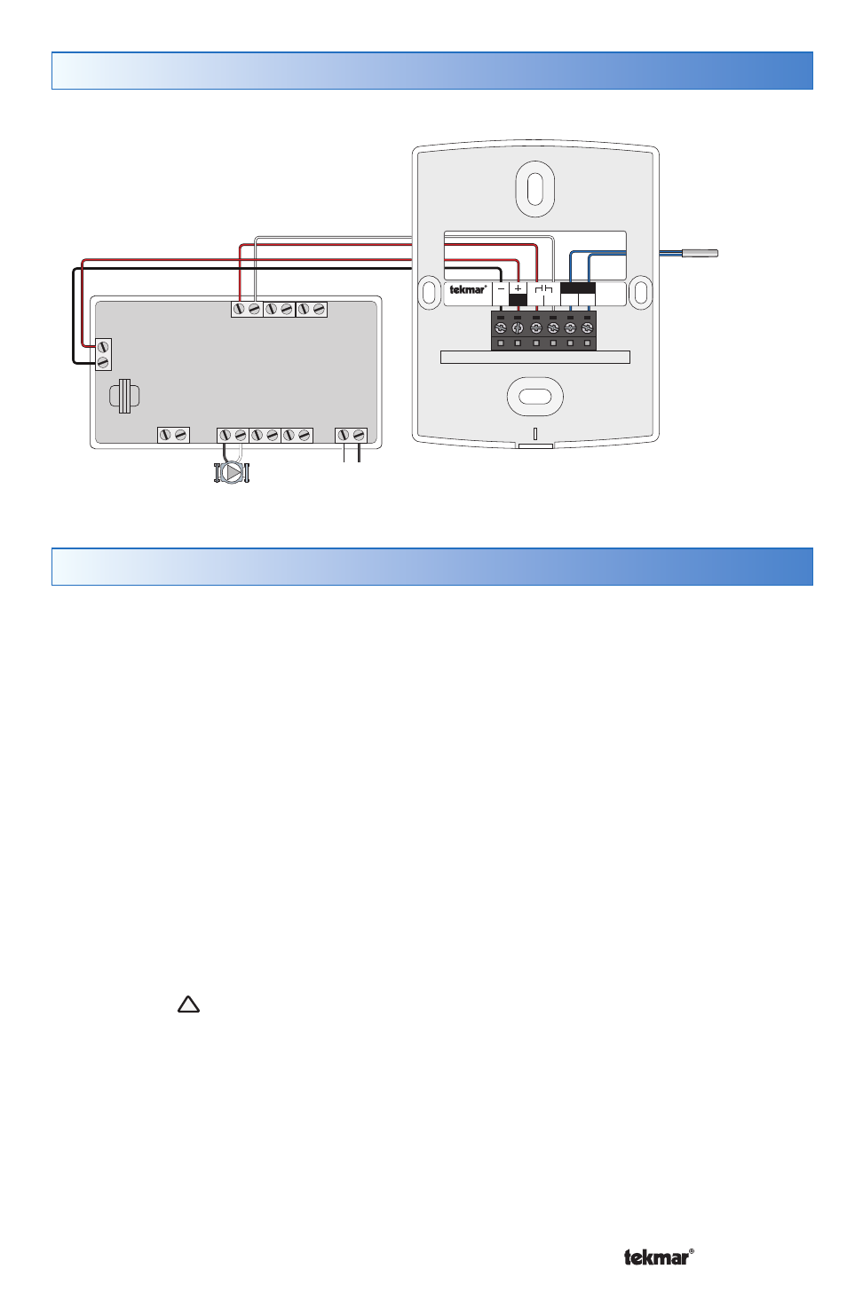
Thermostat Wiring
C
518
R
Rh W1 S1
Com
No Power
R
W
24 V
R
W
H
N
X
X
H
N
H
N
N
H
Com
Switching Relay
Zone 1 Zone 2 Zone 3
Class 2
Transformer
R
W
Zone 1 Zone 2
Zone 3
C
518
R
Rh W1 S1
Com
No Power
Optional
Slab Sensor 079
L
N
Pump