tekmar 509 Thermostat Installation User Manual
Page 8
© 2012
D 508 - 04/12
8 of 16
STEP FOUR
WIRING THE THERMOSTAT
(Refer to the examples on the following page.)
24 V (ac) Power
Connect the 24 V (ac) power to the R and C terminals of the thermostat. This connection
provides power to the microprocessor and display of the thermostat.
Auxiliary Sensor
Either an indoor, slab, or outdoor sensor may be connected to the auxiliary sensor input.
Connect the two wires from the auxiliary sensor to the Sensor terminals.
Heat Relay (Rh – W)
The Heat Relay Rh – W terminals are an isolated output. There is no power available
on these terminals from the thermostat. These terminals are to be used as a switch for
a 24 V (ac) circuit. This circuit can operate a low current 24 V (ac) device directly or an
external relay to enable a line voltage or high current device.
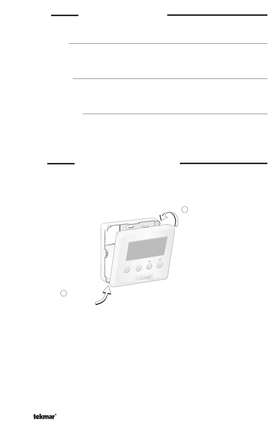
STEP FIVE
INSTALLING THE FRONT COVER
Align the hinges on the bottom of the front cover with the bottom of the thermostat mounting
base. Pivot the front cover around the bottom hinges and push the top against the mounting
base until it snaps firmly in place.
Pivot front
cover around
bottom hinges
Align hinges
on bottom
of front cover
1
2
Menu
Item