tekmar 509 Thermostat Installation User Manual
Page 5
5 of 16
© 2012
D 508 - 04/12
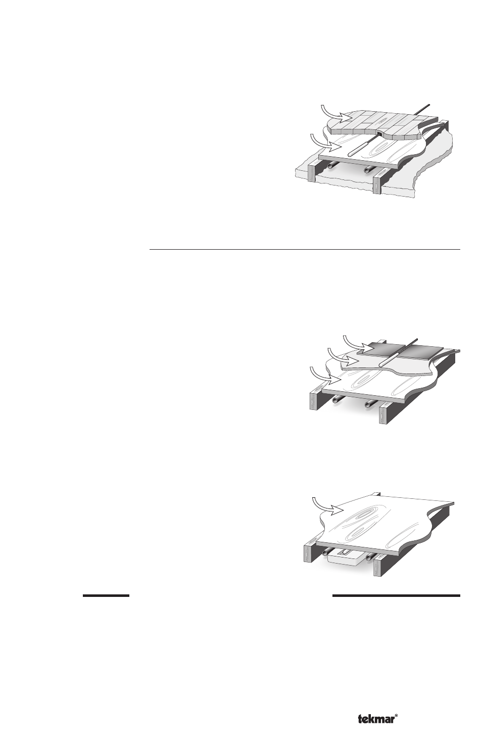
Hardwood
Subfloor
Thick Floor Coverings (greater than 3/8” (10 mm))
If a thick floor covering is to be installed directly to the subfloor, a groove 1/8” (4 mm) wide
by 1/16” (2 mm) deep can be cut into the back of the flooring material to accommodate
the wire for the sensor. Ensure that the sensor is located in such a position that the
attached wire is able to reach to a suitable junction location.
Splices under the floor covering should be
avoided to ensure trouble free operation. A
groove 3/16” (5 mm) wide by 3/16” (5 mm)
deep by 1-3/4” (45 mm) long should be cut to
accommodate the sensor. The sensor should be
located mid way between the heating elements
to ensure a proper temperature reading.
Retrofit Installations
Tile Floor Coverings
If a Slab Sensor 079 is to be installed into an existing tile floor with sufficiently large grout
lines, the sensor and wire can be installed in one of the grout lines between the tiles.
Select a low traffic area of the floor that is mid way between the heating elements for
Tiles
Thin-set
Subfloor
NOTE: If it is not practical to cut a groove in the surface covering, follow the installation
method used for thin floor coverings.
the sensor location. Ensure that the sensor is
located in such a position that the attached wire
is able to reach to a suitable junction location.
Splices within the grout should be avoided to
ensure trouble free operation. Remove the
appropriate grout line and place the sensor and
wire in the floor. Re-grout the area.
Subfloor
Installing the Sensor to the Bottom of a Subfloor
If the sensor is to be installed to the bottom of a subfloor, cut a piece of 1” (25 mm)
thick rigid insulation into a 6” (150 mm) by 6” (150 mm) square. A groove 3/16” (5
mm) wide by 3/16” (5 mm) deep by 1-3/4”
(45 mm) long should be cut into the insulation
to accommodate the sensor. Place the sensor
in the groove and sandwich the sensor between
the insulation and the subfloor. Use a suitable
fastening method to affix the insulation to the
subfloor.
STEP TWO
WIRING AND TESTING THE SENSOR
Caution: Do not run sensor wires parallel to telephone or power cables. If the sensor wires
are located in an area with strong sources of electromagnetic interference, shielded cable
or twisted pair should be used or the wires can be run in a grounded metal conduit.
The Slab Sensor 079 is supplied with 10’ (3 m) of cable. If a longer length is required, 24
AWG or larger wire can be spliced onto the two wires from the sensor. The splices should
be properly soldered and protected in an accessible junction box. Follow the sensor testing
instructions given in this brochure and then connect the wires to the control.