tekmar 256 Boiler Control User Manual
Page 9
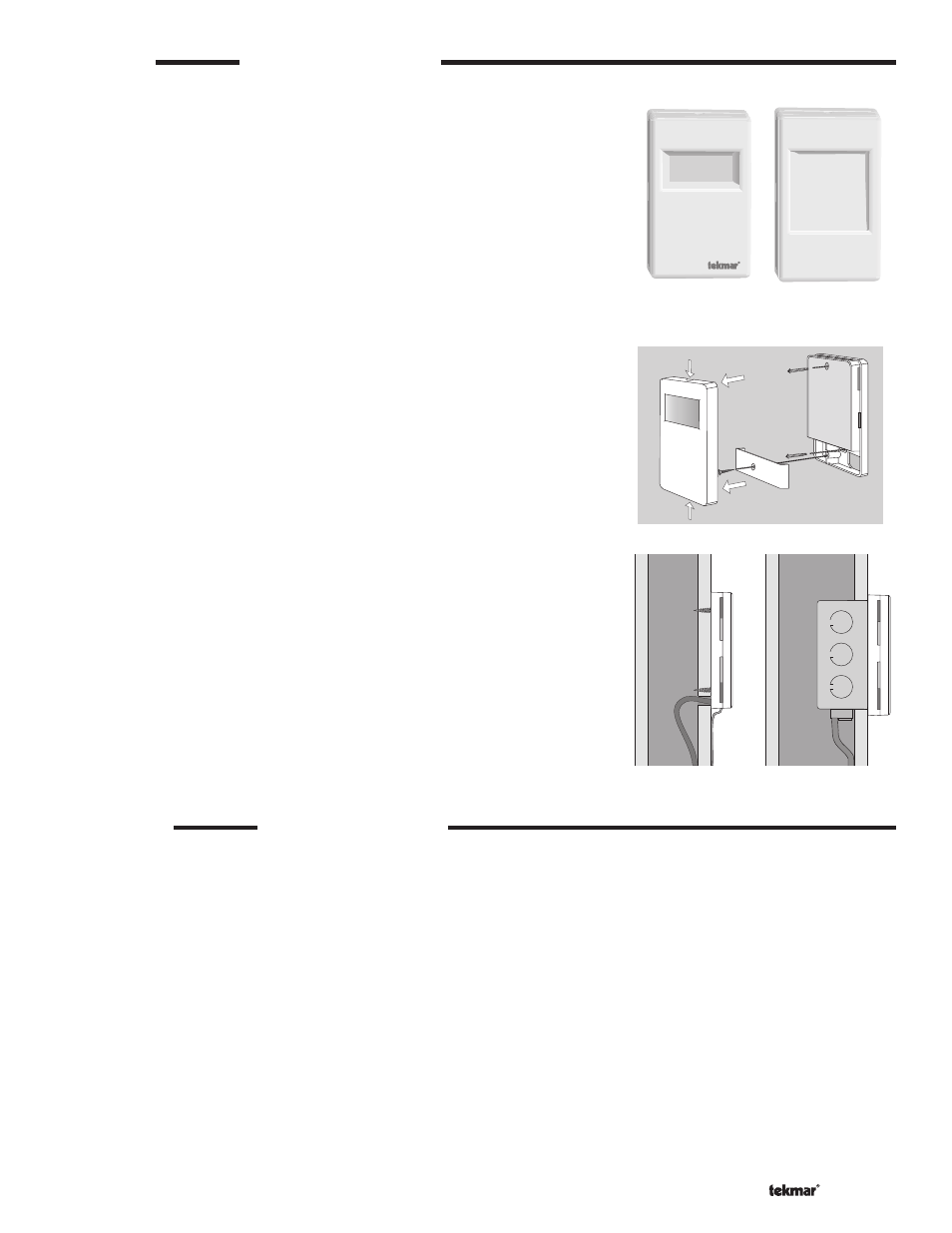
Enclosure C --------------------------------------------------------
Enclosure C is designed for smaller controls and their wiring. This enclosure
has either a large or a small window opening depending on the control used.
Mounting the C Enclosure ------------------------------------------
Grasp the front cover by the fi ngertip grips on the top and bottom of the enclosure
and pull the front cover off. Remove the wiring cover screw. The enclosure is
either mounted fl ush onto a wall or it can be placed onto a 2” x 4” electrical box.
The mounting holes in the enclosure accept #6 screws. Wiring to the control
enters the wiring chamber through the back or bottom of the enclosure. To
reassemble the enclosure, fi rst replace the wiring chamber cover and then push
the front cover onto the enclosure until it snaps into place.
STEP TWO
CONTROL INSTALLATION
STEP THREE
SENSOR INSTALLATION
Caution: Do not run sensor wires parallel to telephone or power cables. If the sensor wires are located in an area with strong sources
of electromagnetic interference, shielded cable or twisted pair should be used or the wires can be run in a grounded metal conduit. If
using shielded cable, the shield wire should be connected to the Sensor Common terminal on the control and not to earth ground.
All electrical wiring terminates in the two wiring chambers on the control. If the control is to be mounted on an electrical box, the wiring
can be roughed-in at the electrical box prior to installation of the control.
Power must not be applied to any of the wires during the rough-in wiring stage.
Install the Outdoor Sensor and Universal Sensor according to the directions on the following page.
9 of 20
© 2011
D 256 - 07/11