tekmar 256 Boiler Control User Manual
Page 14
The installer should test to confi rm that no voltage is present at any of the wires.
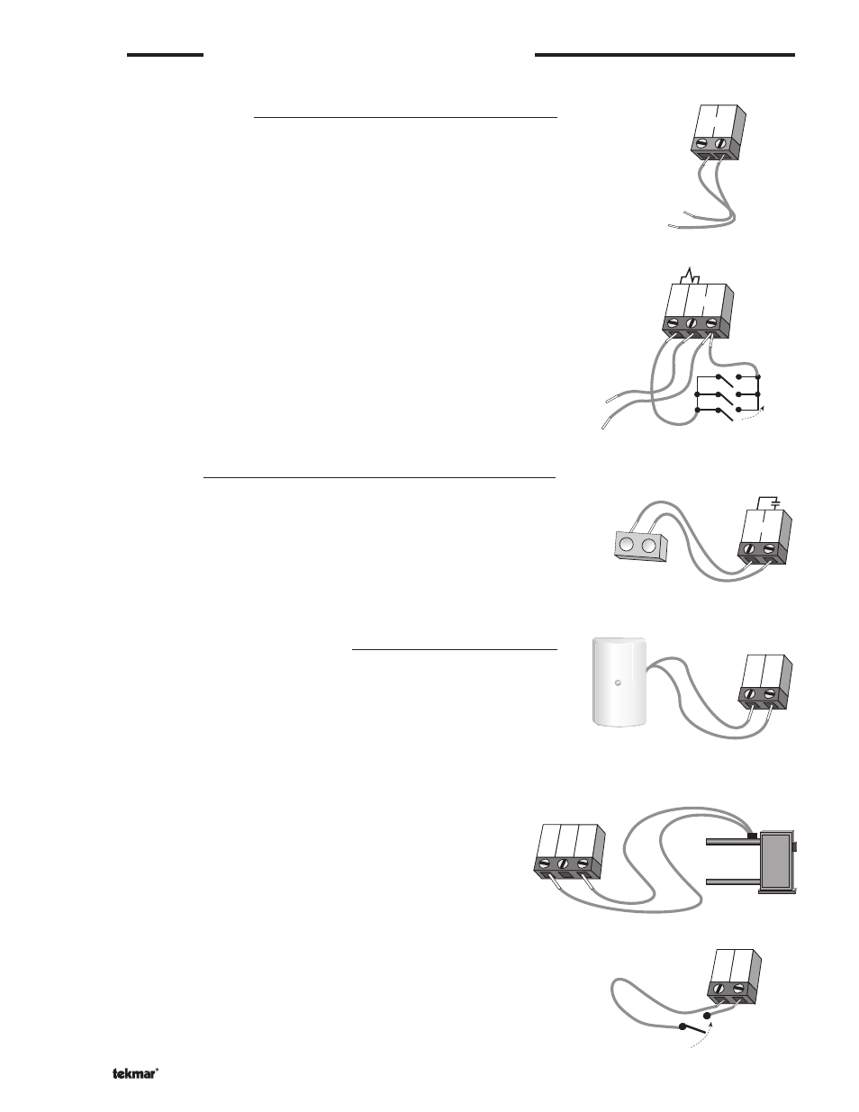
Powered Input Connections
24 V (ac) Power
Connect the 24 V (ac) power supply to the Power R+ and Power C- terminals (8 and
9). This connection provides power to the microprocessor and display of the control.
Boiler Demand
To generate a boiler demand, terminal T(7) must be connected to terminal C-(9)
through a switching device.
Output Connections
Boiler Contact
The Boiler terminals (5 and 6) are an isolated output in the 256. There is no power
available on these terminals from the control. These terminals are to be used as a
switch to either make or break the boiler circuit. When the 256 requires the boiler to
fi re, it closes the contact between terminals 5 and 6.
Sensor and Unpowered Input Connections
Do not apply power to these terminals as this will damage the control.
Outdoor Sensor
Connect the two wires from the Outdoor Sensor to the Out and Com terminals (2 and
3). The outdoor sensor is used by the 256 to measure the outdoor air temperature.
Universal Sensor
Connect the two wires from the Universal Sensor to the Boil and Com terminals
(1 and 3). This sensor is used by the 256 to measure the supply (outlet) water
temperature from the boiler.
Unoccupied Switch
If an external timer (tekmar Timer 033) or switch is used, connect the two wires from
the external switch to the Com and UnO Sw terminals (3 and 4). When these two
terminals are shorted together, the control registers an unoccupied signal.
STEP FIVE
ELECTRICAL CONNECTIONS TO THE CONTROL
© 2011
D 256 - 07/11
14 of 20
8
9
R+
C-
Power
24 V (ac)
C-
T
Power
R+
7
8
9
Boiler demand switches
24 V (ac)
Boiler
5
6
T
T
T
T
2
3
Com
Out
1
Boil
Out
2
3
Com
Boiler
sensor
Timer switch
3
4
Com UnO
Sw