Step five — electrical connections to the control, Powered input connections, Output connections – tekmar 156 Difference Setpoint Control User Manual
Page 7: Sensors and un-powered input connections
7 of 12
© 2010 D 156 - 06/10
The installer should test to confirm that no voltage is present
at any of the wires.
Powered Input Connections
24 V (ac) or 24 V (dc) Power
Connect the 24 V (ac) power supply to the Power C- and
Power R+ terminals (1 and 2). If using a 24 V (dc) power
supply, connect the positive terminal on the DC source to
R+ (terminal 2) and the negative terminal to the C- (terminal
1) on the 156. This connection provides power to the
microprocessor and display of the control.
24 V (dc)
Battery
+
-
L
N
R
OR
C
24 V (ac or dc)
1
2
Power
C-
R+
Step Five — Electrical Connections to the Control
Pump
L
N
3
4
Relay
120 V (ac)
Output Connections
Relay Contact
The Relay terminals (3 and 4) are an isolated output in the
156. There is no power available on these terminals from
the control. These terminals are to be used as a switch
to either make or break the pump circuit. When the 156
requires the pump to run, it closes the contact between
terminals 3 and 4.
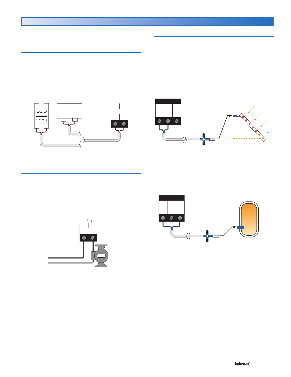
Sensors and Un-powered Input Connections
Do not apply power to these terminals as this will
damage the control.
Source Sensor
Connect the two wires from the Source Sensor 085 to the
Com and Src terminals (5 and 6). The Source Sensor is
used by the 156 to measure the Source temperature.
Insert the Solar Sensor 085 into a temperature well, or
alternatively strap the Solar Sensor 085 on the outlet pipe
close to the heat source with a stainless steel clamp.
No Power
5
6
7
Com Src Stor
S
o
l
a
r
C
o
l
l
e
c
t
o
r
No Power
5
6
7
Com Src Stor
Storage Sensor
Connect the two wires from the Storage Sensor 071 to the
Com and Stor terminals (5 and 7). The Storage Sensor is
used by the 156 to measure the Storage temperature.
Insert the sensor in a well near the bottom of the tank.