Installation, Step one, Step two – tekmar 153 Mixing Setpoint Control User Manual
Page 2: Step three, Step four
2
Installation
Caution
Improper installation and operation of this control could result in damage to equipment and possibly even personal
injury. It is your responsibility to ensure that this control is safely installed according to all applicable codes and
standards.
Step One
Getting ready
Check the contents of this package. If any of the contents listed are missing or damaged, please refer to the Limited Warranty
and Product Return Procedure on the back of this brochure and contact your wholesaler or tekmar sales agent for assistance.
Type 153 includes:
• One Control 153 • One Universal Sensor 071
• One Data Brochure D 153 • One Data Brochure D 001
Other information available:
• Essay E 001
Note: Carefully read the Sequence of Operation section in this brochure to ensure that you have chosen the proper control and
understand its functions within the operational requirements of your system.
Step Two
Mounting
The control is mounted in accordance with the instructions in the Data Brochure D 001.
Step Three
Rough-in wiring
All electrical wiring terminates in the two wiring chambers at the bottom front of the control. If the control is to be mounted on
an electrical box, the wiring can be roughed-in at the electrical box prior to installation of the control (see Brochure D 001).
Standard 18 AWG solid wire is recommended for all low voltage wiring to this control.
Caution: Power should not be applied to any of the wires during this rough-in wiring stage.
• Install the Universal Sensor 071 according to the instructions in Data Brochure D 070 and run the wiring back to the control but
don’t connect.
• Install a 24V (ac) Class 2 transformer with a minimum 5 VA rating close to the control, and run the wiring from the transfor-
mer to the control.
A Class 2 transformer must be used. Do not connect any of the transformer terminals to ground.
• Or provide 24 V DC power of at least 0.03 A and run wiring to the control location.
Step Four
Testing and connecting the wiring
Caution
These tests are to be performed using standard testing practices and procedures and should only be carried out by
a properly trained and experienced technician.
A good quality electrical test meter, capable of reading from at least 0 — 200 Volts AC, and at least 0 — 2,000,000 Ohms,
is essential to properly test this control.
At no time should voltages in excess of 28V be measured as power supply to this control.
Test the sensor
This test must be performed
before power is applied to the control and before a sensor is connected to the terminal strip. Test
the sensor(s) according to the instructions printed in the enclosed Data Brochure D 001.
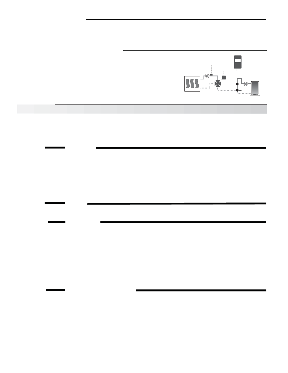
Supply and Boiler Return Sensor Operating Mode
• If a Boiler Return Sensor option is installed, then whenever the measured boiler
return water temperature is near the return minimum, the control starts to close
the 4-way mixing valve in order to divert more hot water back to the boiler. The
Return (2) indicator will be flashing at a slow rate to indicate mixing valve is being
controlled by the Boiler Return (2) sensor reading. When using a Boiler Return
(2) sensor for minimum boiler return protection, it is essential that there always
be water flow past the Boiler Return (2) sensor whenever there is Supply (1)
demand.
Supply Sensor Operating Mode
• If only a Supply Sensor is installed, the control regulates the supply water temperature through applying a floating output signal
to the actuating motor. Supply (1) adjustment sets the setpoint temperature. Adjusting the throttling range will set the temperature
range in which floating output action occurs.
Actuating
Motor
4-Way Valve
Heating System
Boiler Return (2)
Sensor 071
Supply (1)
Sensor 071
M
153
• Install the wiring from the actuating motor to the control.