Settings, Program mode, Display mode power on – tekmar 152 Two Stage Setpoint Control User Manual
Page 3: Operating mode, Max. 24 volts
Electrical connections
Power and output connections — Caution, Maximum 24 Volts A.C. or D.C.
Connect: — the power supply to terminals
C — R +(1 and 2)
— the heating/cooling device circuit 1 to terminals
Relay 1 (3 and 4)
— the heating/cooling device circuit 2 to terminals
Relay 2 (5 and 6)
Sensor connection(s) — Caution, voltage is never applied to these terminals
Connect:
Sensor 071 to terminals
S1 Sen and Com (7 and 8)
Sensor 071 to terminals
S2 Sen and Com (7 and 9) Optional
3
Test the sensor (s)
This test must be performed
before power is applied to the control and before a sensor is connected to the terminal strip. Test
the sensor(s) according to the instructions printed in the enclosed Data Brochure D 070.
Test the power supply
• Ensure that the wires from the power supply transformer are not touching each other, any other wires or ground. Turn on the
power and, using an AC voltmeter, you should measure between 20 and 28 volts at the secondary side of the transformer.
• Turn off the power and complete the electrical connections to the terminal strip of the control.
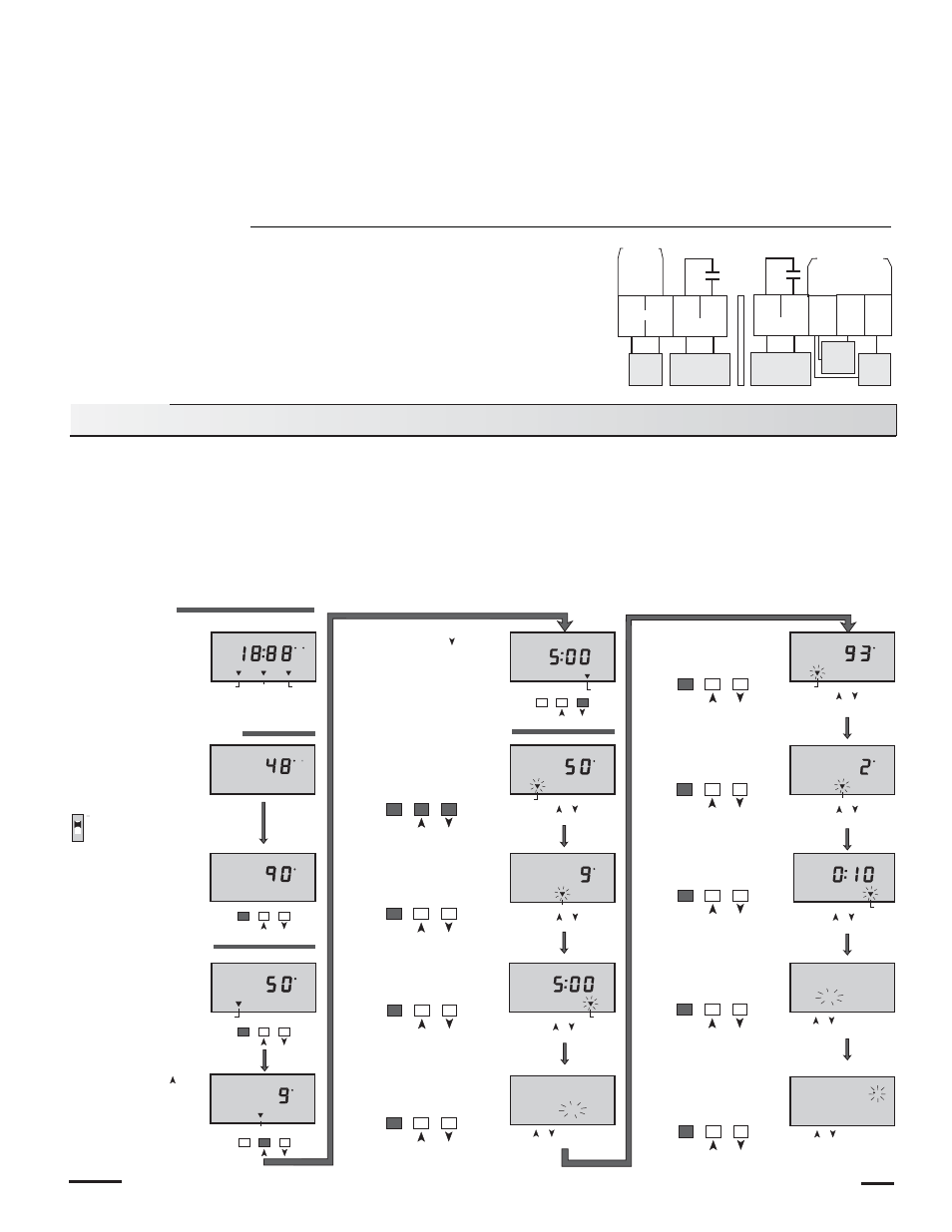
The digital display on the Two Stage Setpoint Control 152 has the following uses:
• To display the actual temperature(s) during normal operating mode.
• To allow the user to view and program the various control settings.
• To display control operation. ("HEAT" display element comes on when either relay closes to operate a heat source and "COOL"
display element comes on when either relay closes to operate a cooling device.)
• To display sensor faults. (Display will show "Err" when a sensor is either disconnected, short circuited or out of temperature range.)
• To display program faults. (Display will show "Prgm Err" when the “Heat/Cool” single sensor mode is incorrectly programmed.)
The following diagram illustrates how to operate the keypad buttons in order to view settings and program the control.
Do not apply
power here
24V
power
supply
Heating/Cooling
device circuit #1
Heating/Cooling
device circuit #2
1
C–
2
R+
3
4
10A
10A
Relay 1
Relay 2
5
6
7
Com
Sen
S1
Sen
S2
Sen
8
9
Sensor
#1 (071)
Sensor
#2 (071)
Power
Settings
The control automatically goes back to operating mode when the buttons are left alone for 20 seconds
The control automatically goes back to operating mode when the buttons are left alone for 20 seconds
Item
Item
Item
Item
Item
Item
Push or to
change Differential
Push or to
change Delay
Push or to select between
Heating or Cooling operation
Item
Push or to
change Setpoint
Item
Push or to
change Setpoint
Item
Push or to
change Differential
Item
Item
Push or to
change Delay
Item
Push or to select between
Heating or Cooling operation
Item
Push or to select between
Fahrenheit or Celsius scales
2 Sensors
Dip Switch Up
If two sensors are are in use.
PROGRAM MODE
Pushing the "Item" button,
"PRGM 2" appears, and the
Setpoint (2) pointer will
flash.
PRGM
F
Setpoint
When the control is
powered-up, all display
elements turn on.
DISPLAY MODE
POWER ON
When in operating mode,
the actual sensor
temperature(s) are
displayed.
After approximately 5 seconds, the control
automatically goes into operating mode.
OPERATING MODE
Push and Release the
"Item" button. The display
will toggle between sensor
1 and 2.
1
Delay
1
PRGM
COOL
PRGM
F
Differential
2
PRGM
F
C
1
Push all three buttons
at the
same time. "PRGM 1" will
appear and the Setpoint (1)
pointer will flash. The control
will be in programming mode.
Pushing the "Item"
button changes the
flashing pointer to
Differential (1)
Pushing the "Item" button
changes the flashing pointer
to Delay (1)
Pushing the "Item" button
allows Heating or Cooling (1)
operation to be selected
Pushing the "Item" button
allows the Fahrenheit or
Celsius scale to be
selected
Pushing the "Item" button
changes the flashing pointer
to Differential (2)
Pushing the "Item" button
changes the flashing pointer
to Delay (2)
Pushing the "Item" button
allows Heating or Cooling
(2) operation to be selected
Push and Hold the "Item"
button. The programmed
Setpoint 1 and then
Setpoint 2 will be displayed.
Push and Hold the
button. The programmed
Differential 1 and then
Differential 2 will be
displayed.
Push and Hold the
button. The programmed
Delay 1 and then Delay 2
will be displayed.
Setpoint
F
1
HEAT
COOL
F
C
1
PRGM
F
Differential
1
PRGM
Delay
1
PRGM
Delay
2
PRGM
HEAT
COOL
2
F
Differential
1
PRGM
HEAT
COOL
F C
Setpoint
Differential
Delay
1
2
PRGM
F
Setpoint
2
F
2
F
HEAT
COOL
COOL
COOL
Max. 24
Volts