Installation, Step four, Step one – tekmar 152 Two Stage Setpoint Control User Manual
Page 2: Step two, Step three, 2 stage cool control, Heat/cool control, 2 stage heat control
Single Sensor Mode
When using a single sensor, the sensor controls the action of both output relays. Any
combination of “HEAT/HEAT” , “HEAT/COOL”, “COOL/COOL” may be utilized. When
using the Two Stage Setpoint Control 152 in a “HEAT/COOL” installation with only a single
sensor, a 3 °F difference must be programmed between the heat setpoint plus 1/2 its
differential, and the cool setpoint minus 1/2 its differential for operation. This ensures that the
heating and cooling systems cannot operate at the same time.
Step Four
Testing and connecting the wiring
Caution
These tests are to be performed using standard testing practices and procedures and should only be carried out by
a properly trained and experienced technician. A good quality electrical test meter, capable of reading from at least
0 — 200 Volts AC, and at least 0 — 2,000,000 Ohms, is essential to properly test this control. At no time should voltages
in excess of 28Vac be measured at any of the wires connected to this control.
2
Installation
Caution
Improper installation and operation of this control could result in damage to equipment and possibly even personal injury.
It is your responsibility to ensure that this control is safely installed according to all applicable codes and standards.
Step One
Getting ready
Check the contents of this package. If any of the contents listed are missing or damaged, please refer to the Limited Warranty
and Product Return Procedure on the back of this brochure and contact your wholesaler or tekmar sales agent for assistance.
Type 152 includes:
• One Control 152 • One Universal Sensor 071
• Data Brochure D 152 • Data Brochure D 001 • Data Brochure D 070 • Appl. Brochure A 152
Other information available: • Essay E 001
Note: Carefully read the Sequence of Operation section in this brochure to ensure that you have chosen the proper control and
understand its functions within the operational requirements of your system.
Step Two
Mounting
The control is mounted in accordance with the instructions in the Data Brochure D 001.
Step Three
Rough-in wiring
All electrical wiring terminates in the two wiring chambers at the bottom front of the control. If the control is to be mounted on
an electrical box, the wiring can be roughed-in at the electrical box prior to installation of the control (see Brochure D 001).
Standard 18 AWG solid wire is recommended for all low voltage wiring to this control.
Caution: Power should not be applied to any of the wires during this rough-in wiring stage.
• Install the Universal Sensor(s) 071 according to the instructions in Data Brochure D 070 and run the wiring back to the control
but do not connect.
• Install a 24 V power supply, and run the wiring from the power supply to the control with 24 V (ac) power. A Class 2 trans-
former must be used. Do not connect any of the transformer terminals to ground.
• Install the wiring from the heating/cooling device(s) control circuit(s) to the appropriate relay on the control.
• If the control setpoints 1 and/or 2 are programmed for “Cool” the control turns on the relay and shows the “COOL” display element
when the sensor temperature is (a) — 1/2 the differential setting above the setpoint,
and (b) — the delay has timed out. When the
sensor temperature drops 1/2 the differential setting below the setpoint, the control switches its relay off and the delay starts to time
out.
Desired temperature
this example
40°F(4°C)
Temperature
W
armer
Cooler
Time
Differential
this example
10°F(5°C)
45°F(7°C)
35°F(2°C)
Te
m
pe
ra
tu
re
fa
ll
CONTROL RELAY (COOLING)
ON OFF
Te
m
pe
ra
tu
re
ris
e
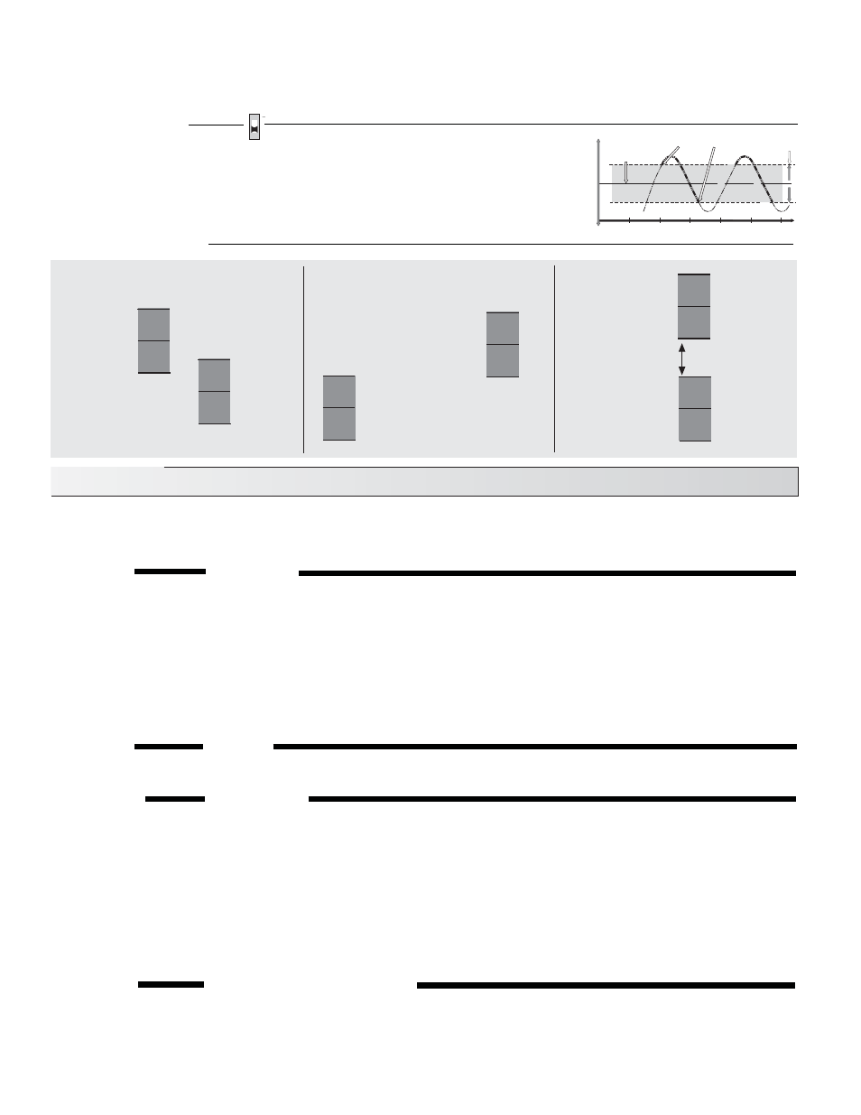
Programming Examples
2 Stage Cool
Control
Stage 2
Stage 1
70 °F
+1/2 diff 2
66 °F
-1/2 diff 2
73 °F
-1/2 diff 1
76 °F
Setpoint 1
68 °F
Setpoint 2
off
off
on
on
79 °F
+ 1/2 diff 1
Heat/Cool
Control
Stage 2 Heat
Stage 1 Cool
minumum 3 °F
difference required
99 °F
+ 1/2 diff 2
95 °F
- 1/2 diff 2
Stage 2
97 °F
Setpoint 2
2 Stage Heat
Control
off
on
79 °F
+1/2 diff 2
77 °F
-1/2 diff 2
78 °F
Setpoint 2
off
on
102 °F
+ 1/2 diff 1
98 °F
-1/2 diff 1
Stage 1
100 °F
Setpoint 1
off
on
2 Sensors
Dip Switch Down
79 °F
-1/2 diff 1
80 °F
Setpoint 1
off
on
81 °F
+ 1/2 diff 1