tekmar 095 Snow Sensor User Manual
Page 3
© 2013
095_D - 05/13
3 of 8
A Watts Water Technologies Company
Step 3 - Rough In Wiring
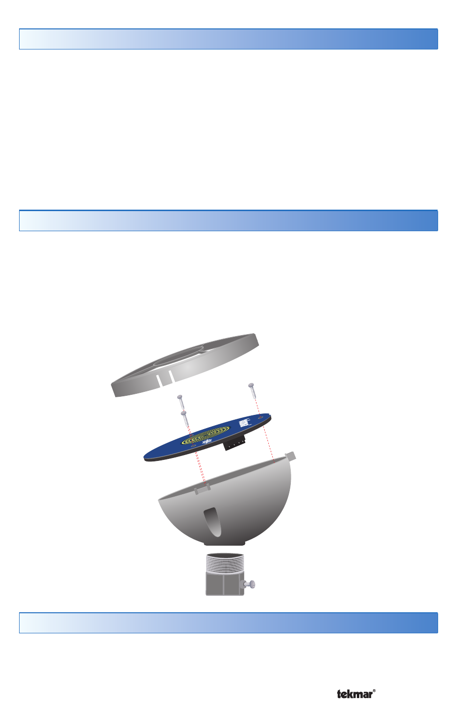
Step 4 - Disassembly
Install a nominal 1/2” (16 mm) PVC or metal conduit from the tekmar Snow Melting
Control to the chosen sensor location. Pull 4 conductor 18 AWG wire from the
sensor location to the control location through the conduit. The maximum wire
length between the sensor and the control is 500’ (150 m).
If using PVC conduit, do not run the wires parallel to telephone or power lines. If the
sensor wires are located in an area with strong sources of electromagnetic noise,
shielded cable or twisted pair should be used. If using shielded cable, one end
of the shield wire should be connected to the Com terminal on the Snow Melting
Control and the other end should remain free. The shield must not be connected
to earth ground.
1. Remove the outer ring by pulling up on the three catches.
2. Remove the three screws.
3. Remove the blue sensor disk from the sensor enclosure.
Avoid scratching any part of the surface of the blue sensor disk.
Scratches will result in corrosion not covered by warranty.
Step 5 - Painting the Sensor
The sensor enclosure is made of an off-white plastic material that is UV stable.
The plastic enclosure may be spray painted to match the color of the building. Do
not paint the blue sensor disk as this will damage the sensor.
Outer Ring
Blue Sensor Disk
Sensor
Enclosure
Conduit Adapter
(not included)