tekmar 086 Humidity & Temperature Sensor User Manual
Page 4
© 2012
086_D - 08/12
4 of 8
A Watts Water Technologies Company
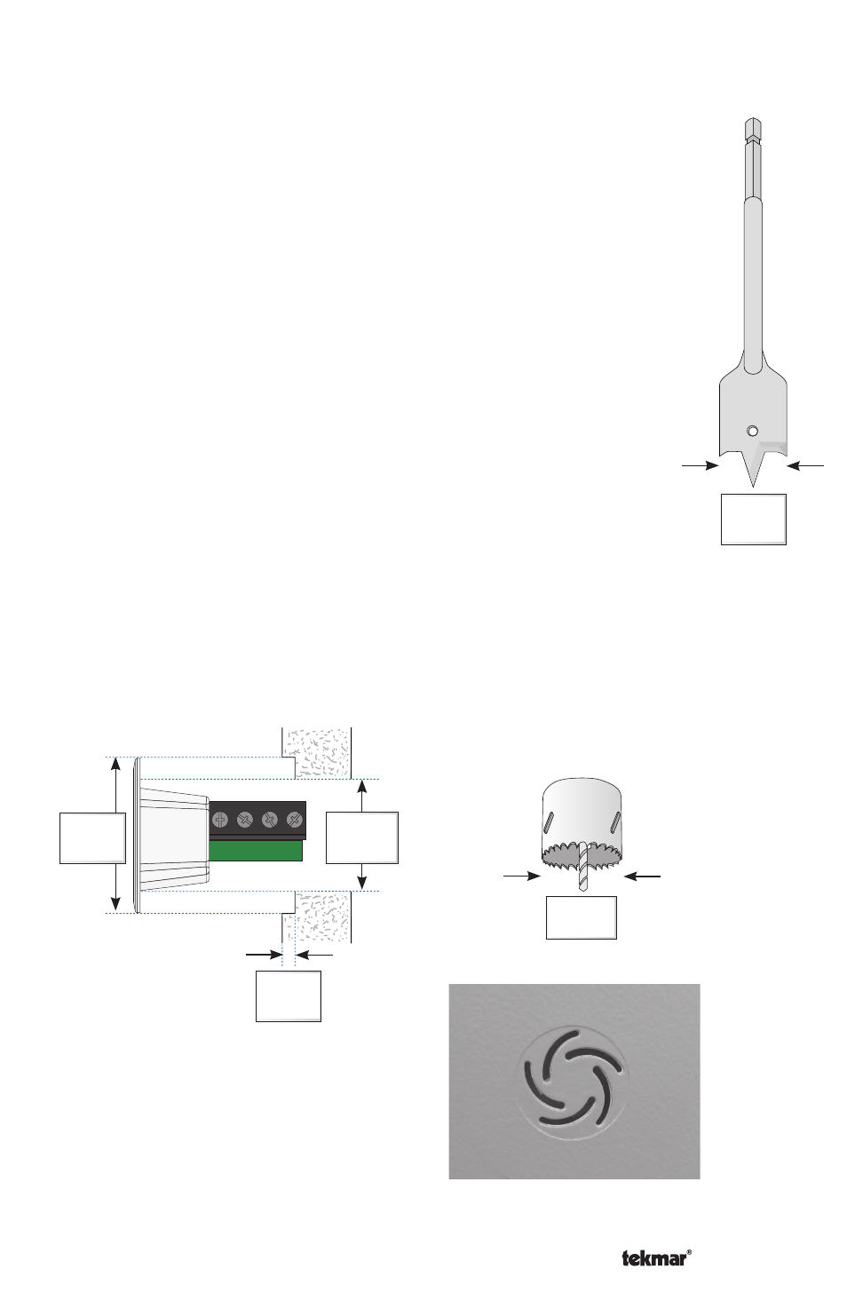
1”
(25.5 mm)
1-1/2”
(38.0 mm)
1/8”
(3.0 mm)
A. Use a 1-1/2” (38.0 mm) spade bit to drill a recess hole lightly into
the drywall to a depth no more than 1/8” (3.0 mm).
B. Use a 1” (25.5 mm) hole-saw and place the guide bit into the center
hole created by the spade bit and drill through the drywall.
C. Sand the surface of the drywall around the hole to remove the
raised paper edge from drilling.
D. Pull the excess wire through the hole.
E. Follow the directions in Step Five - Wiring the Sensor.
F. Use a straight edge (a square or a level) to push the sensor flush
with the surface of the drywall. Press 2 to 3 times in each direction
(90 deg and 0 deg) repeatedly until flush. Do not attempt to press it
in in one motion as the sensor may tilt. The sensor is held in place
by the taper of the enclosure (no fasteners required). Leave the
front disc sticker in place.
G. Use a mud trowel to mud over the entire sensor.
H. Once mud dries, sand the surface of the sensor until the entire
front disc sticker is completely visible. This ensures the shallowest
circular mark.
True Flush Mount
----------------------------------------------------
----------------------------------------------------
Spade Bit
1-1/2”
(38.0 mm)
Hole Saw
1”
(25.5 mm)
Photo of actual 086 flush mount installed
I. Remove front disc sticker.
J. Paint the wall including the sensor using a paint roller. The slotted grill holes
must be kept open and free of paint. This can be achieved by using the paint
roller that is mostly wrung out of paint.