Connector pin assignments, See “connector pin, Connect or pin assignments – Sound Devices PIX 250i User Manual
Page 77
PIX 250i User Guide
71
Connect
or Pin Assignments
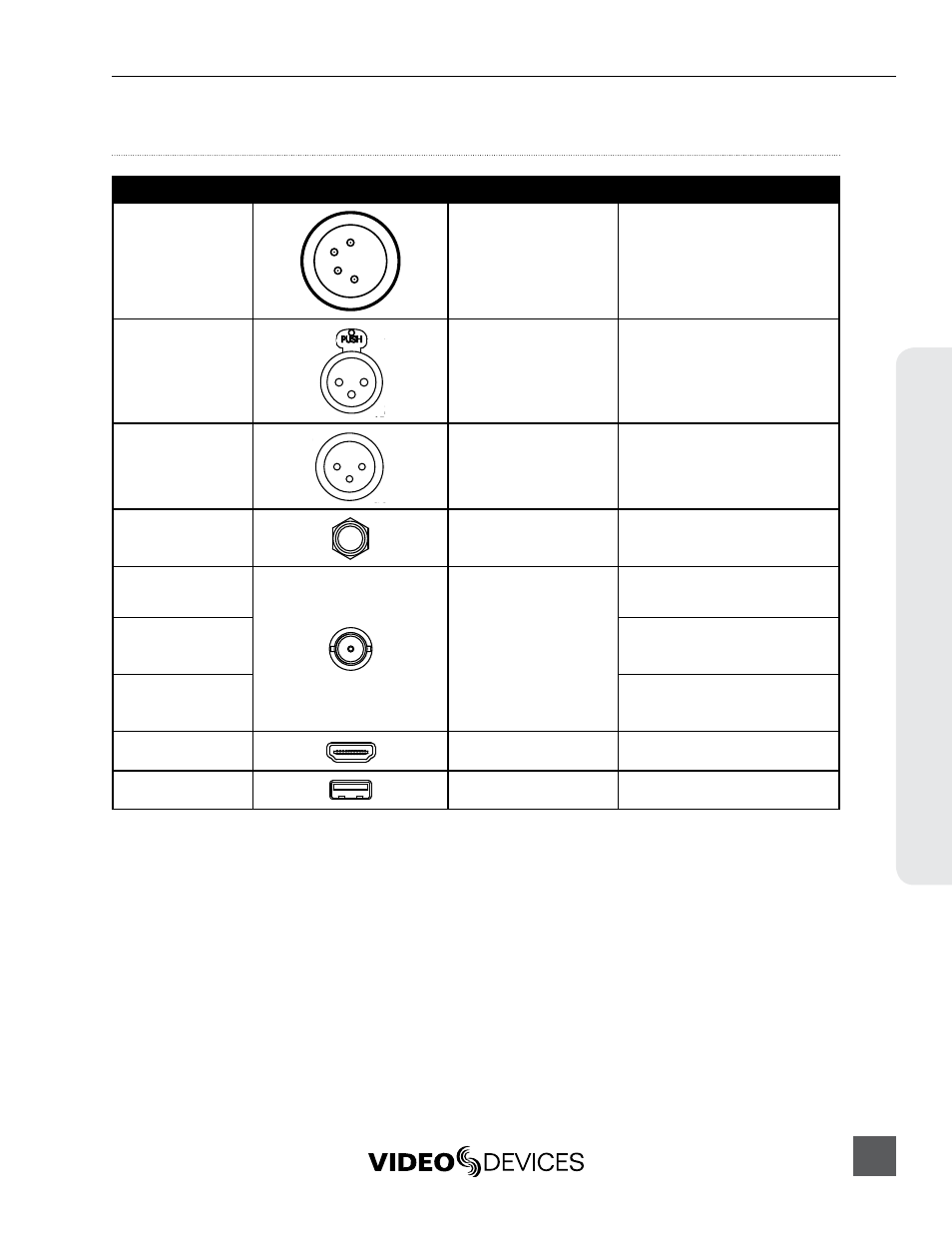
Connector Pin Assignments
Connector
Pin Assignments
Notes
XLR4M
(DC Input)
1–ground
2–float
3–float
4–DC+
Pins 2 and 3 unused. When using
a single power source, use Primary
connector (top). (
XLR-F (2)
(Analog Audio inputs)
1–ground
2–signal (+)
3–signal (-)
Mates with XLR-Male connector
20k ohm input impedance, line level,
active-balanced
XLR-M (2)
(Analog Audio out-
puts)
1–ground
2–signal (+)
3–signal (-)
Mates with XLR-Female connector
20k ohm input impedance, line level,
active-balanced
TRS
(Headphone output)
Tip–signal L
Ring–signal R
Sleeve–signal ground
Mates with TRS jack.
BNC (2)
(Timecode input &
output)
Center pin–signal
Sleeve–ground
Mates with BNC male connector
Unbalanced, coaxial connection
BNC (2)
(SDI input & output)
Mates with BNC male connector
Unbalanced, coaxial connection, 75
ohm connectors recommended
BNC (2)
(Genlock or Word-
clock input & output)
Mates with BNC male connector
Unbalanced, coaxial connection, 75
ohm connectors recommended
HDMI (2)
(HDMI input & output)
Standard HDMI
Mates with HDMI Type A Plug (male)
USB-A (1)
Keyboard Input
Standard USB-A receptacle
For use with USB Keyboards only.
Data transfer is not supported