Ext er nal contr ol – Sound Devices PIX 250i User Manual
Page 57
PIX 250i User Guide
51
Ext
er
nal Contr
ol
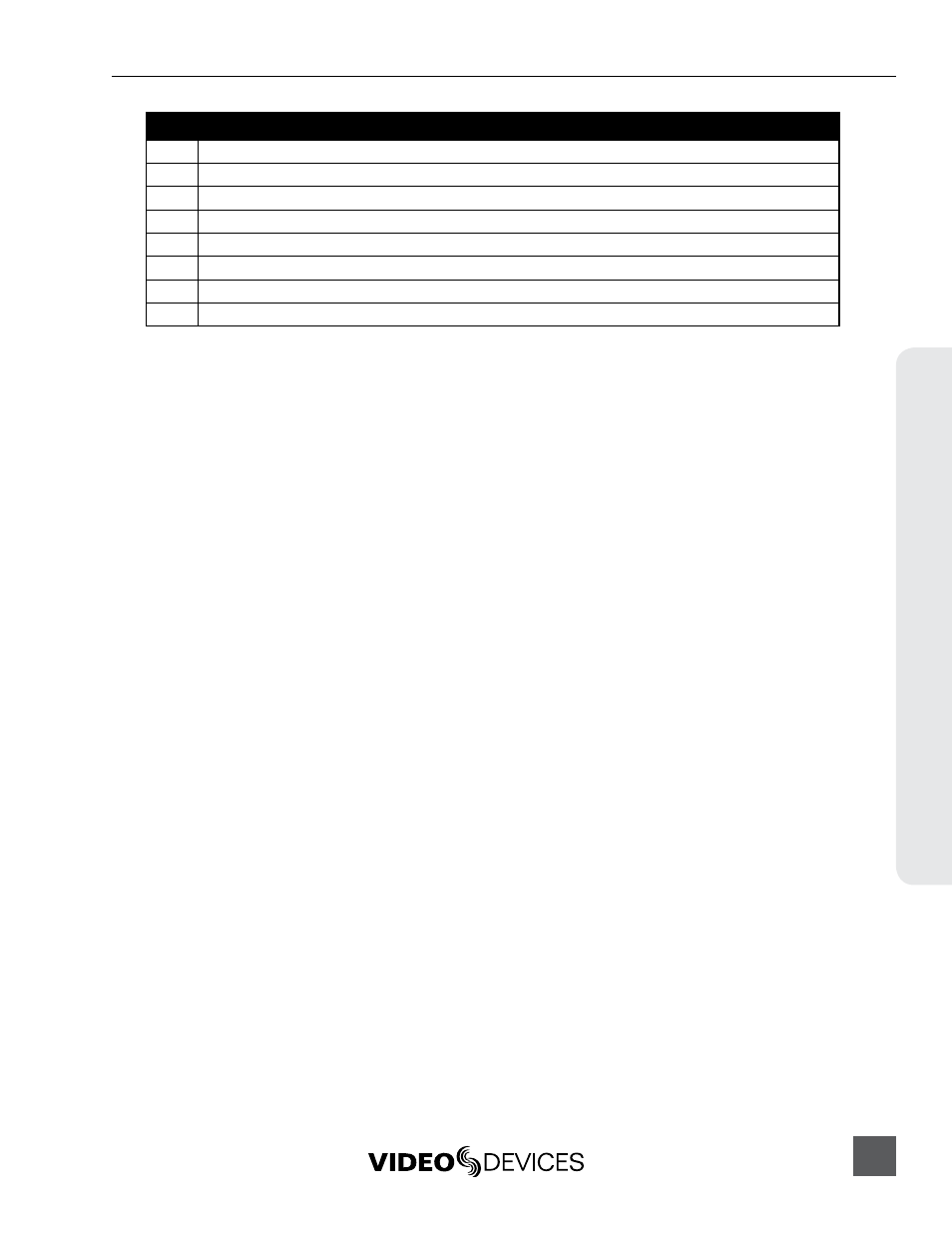
Pin
Function
2
Play Input. Triggers PIX 250i play.
3
Stop Input. Triggers PIX 250i stop.
4
(unused)
5
(unused)
6
REC Output. Activates upon PIX 250i record.
7
Play Output. Activates upon PIX 250i play.
8
Stop Output. Activates upon PIX 250i stop.
+5V
+5V DC Output. Constant source of +5V for triggering logic high connections.
GPIO inputs (pins 1, 2, and 3) and GPIO outputs (pins 6, 7, and 8) can be set to “logic high” or “logic
low”. Logic high connections will trigger to the presence of +5V (GPIO input) or output +5V when
the function is active (GPIO output). Logic low connections will trigger when connected to ground
(GPIO input) or become connected to ground when the function is active (GPIO output).
To configure GPIO connections as logic high or logic low, access Setup Menu option
[Remote Control - GPIO Inputs] or [Remote Control - GPIO Outputs].
The GPIO Outputs can be used to drive LEDs with a proper series resistor. Resistor values will vary
from LED to LED, 470 ohms is a good starting point.