Speaker connections, Dipole or bipole system connections, Mode control – Revel Embrace User Manual
Page 16: Connector panel
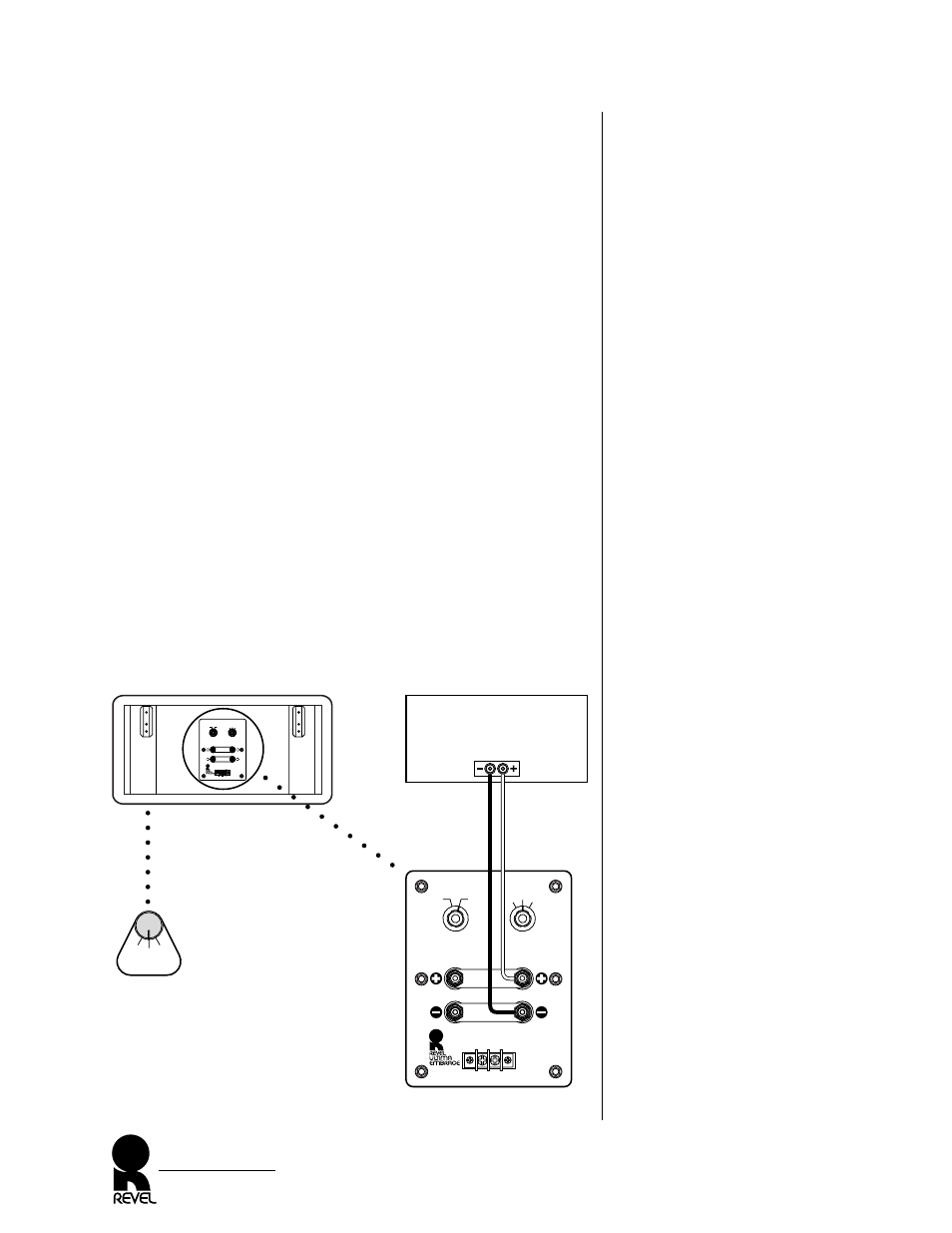
Figure 16. How to connect the
EMBRACE for dipole or bipole
operation, the most common type
of installation.
NOTE: Do not remove the gold-
plated shorting straps.
SPEAKER CONNECTIONS
The EMBRACE surround speakers can be connected to your sys-
tem in a variety of ways, as discussed in the following sections.
Also, please observe these points:
• Use high-quality speaker cable of sufficient gauge (maximum
total loop resistance of 0.1 ohms per channel) with high-quali-
ty connectors between the speaker and your audio system.
Consult your Revel dealer as to specific recommendations for
your application.
• Turn off all audio system power before making any connections.
• Read the owner’s manuals that were included with your audio
components to confirm their connection procedures.
• Verify correct polarities (i.e., + to + and - to -) when making
connections. Failure to do so will degrade the EMBRACE’s
performance.
DIPOLE OR BIPOLE SYSTEM CONNECTIONS
For dipole or bipole operation, simply leave the EMBRACE short-
ing straps in place. Using correct polarity, connect either set of ter-
minals to an amplifier channel output, as shown in Figure 16.
EMBRACE
Owner’s Manual
16
EMBRACE Rear
High Frequency
Level (dB)
Rear Wall
Proximity
Connect for
Normal Operation
Connect for
Normal Operation
Remove Straps
for Dual Drive
Remote
Dipole /Bipole
Chatsworth
California
Made in U.S.A.
Front
Rear
0
-1
+1
Normal
Near
Rear
Wall
High Frequency
Level (dB)
Rear Wall
Proximity
Connect for
Normal Operation
Connect for
Normal Operation
Remote
Dipole /Bipole
Serial No. xxxx
Chatsworth
California
Made in U.S.A.
Front
Rear
0
-1
+1
Normal
Near
Rear
Wall
Set MODE Control To
“Dipole” Or “Bipole”
Mode
Control
(on front)
Remote
Dipole
Bipole
Connector Panel
Amplifier
(rear)
(one channel shown)
Leave
Shorting Straps
In Place