Revel Embrace User Manual
Page 13
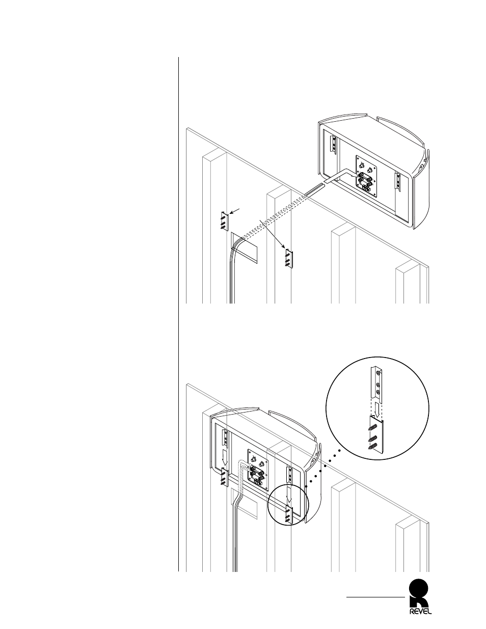
Figure 11. Routing and
connecting the speaker wire.
Figure 12. Mounting an
EMBRACE on a wall.
6. At each site, route the speaker wire through the cutout and,
using correct polarity, attach the ends to the terminals on the
rear of the EMBRACE, as shown in Figure 11. Also refer to
Speaker Connections starting on page 16.
7. Slide each cabinet securely down onto the wall brackets, as
shown in Figure 12. Remove the tape and template after
mounting each EMBRACE.
EMBRACE
Owner’s Manual
13
High Frequenc
y
Le
vel (dB)
Rear W
all
Pr
oximity
0
-1
+1
Near
Rear
Wall
Normal
Fr
ont
Remote
Dipole
/Bi
Chats
wo
rth
Calif
ornia
Made in U
.S.A.
OUTER
BRACKETS
(installed
in studs)
EMBRACE
(rear view)
wallboard
(top)
stud
stud
cutout
speaker
wires
High Frequenc
y
Le
vel (dB)
Rear W
all
Pr
oximity
0
-1
+1
Near
Rear
Wall
Normal
Fr
ont
Remote
Dipole
/Bi
Chats
wo
rth
Calif
ornia
Made in U
.S.A.
EMBRACE
(rear view)
wallboard
(top)
INNER BRACKET
On EMBRACE
OUTER BRACKET
On Wall