Fixture lamp mode – Kino Flo Image 85/45 DMX Series User Manual
Page 14
14
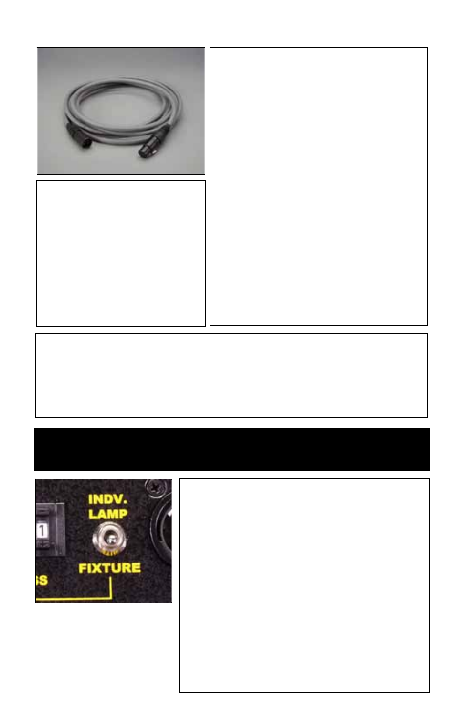
DMX Cables
The Fixture uses five-pin XLR male and
female connectors to receive DMX signals
from the Dimmer Board and jumper the
Fixtures in a series. DMX pin-out wiring
follows the USITT DMX512 standard:
Pin 1: Shield
Pin 2: Data -
Pin 3: Data +
Pin 4: Spare -
Pin 5: Spare +
Note: Pin four and five in the Fixture are
connected internally as Pin four to four
and Pin five to five. Connecting Pin four
and five as the pass-thru allows secondary
data to be passed through for other
equipment.
Do Not use Microphone Cables
and other general purpose,
two-core Cables designed for
audio or signaling use. They are not
suitable for DMX512. Problems due
to incorrect cabling may not be
immediately apparent. Microphone
Cables may appear to work fine,
but systems built with such Cables
may fail or be prone to random
errors. Cable must comply with
EIA-485 (RS485).
Fixture Lamp Mode
Setting the unit to Fixture mode allows the
user to re-create the “Inside-Out" pattern of
the manual switch.
One dimmer channel controls the lamps,
a second channel the HO/STD setting.
Assign the first address to a dimmer
channel. Adjusting the slider up or down
sets the number of lamps to be turned on.
For HO/STD control on Image 85, assign
the 9
th
address to the second dimmer slider.
For Image 45, assign the 5
th
address to the
second dimmer. From 0%~50% operates all
the lamps in the fixture at HO mode, from
50%~100% in the STD mode.
NOTE: If a fixture or Ballast loses its DMX signal it will hold its last DMX
command. For this reason it is important to turn a Fixture or Ballast off using
the DMX commands. For example, if you try to turn off the lights by turning off
the dimmer board, the lights will remember their last DMX command and stay
on. The Fixture or Ballasts require a DMX “Off” or “Black-Out” command in
order to turn off.