2 the display, 3 the touch pad, 4 vapor purge – HF scientific AccUView UV %Transmission Monitor User Manual
Page 8
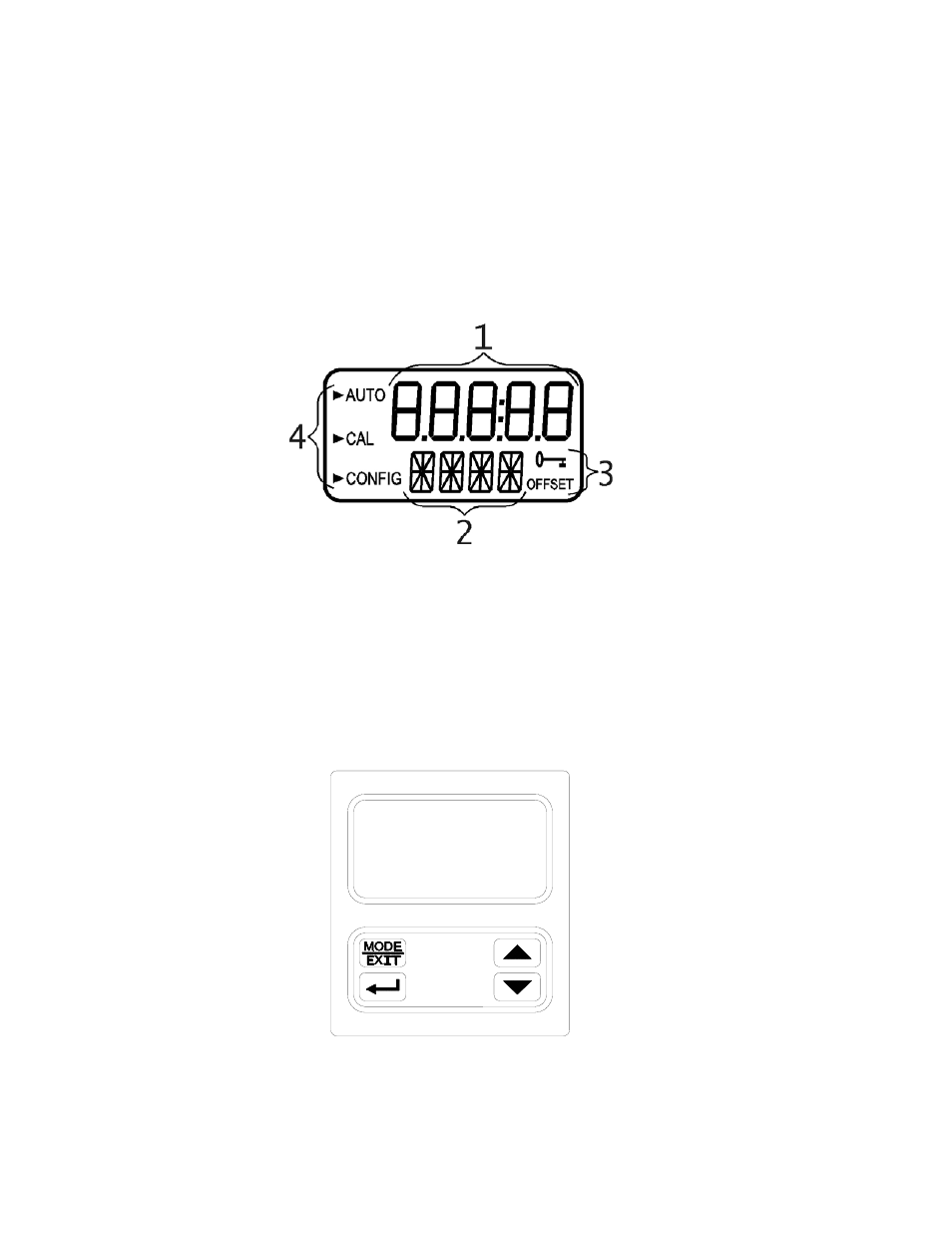
1.2 The Display
Figure 1 illustrates all the items that can appear on the display. The upper row of the
display (1) is used for reporting the % T levels and to provide user guidance in the
customer setting routine. The lower row of the display (2) is used to communicate error
messages and provide user guidance. All error messages will be added to a queue along
with the units (%T). The display has two icons (3) that are used to indicate the use of
access code and offset mode. In addition, mode arrows (4) are used to indicate the current
instrument operating mode; AUTO (normal operation), CAL (calibration) and CONFIG
(configuration).
Figure 1 – Display used in the instrument.
All items used on the display are shown in this figure
1.3 The Touch Pad
Figure 2 illustrates the touch pad. The touch pad has four buttons: MODE/EXIT,
↵, t,
and
u. The MODE/EXIT button is used to cycle between the three operational modes of
the instrument: CAL, CONFIG, and AUTO (Measurement) mode. The
↵ button enters
the option (or mode that is highlighted or chosen. The
tand u buttons are used to change
settings.
Figure 2: The AccUView touch pad.
AccUView (6/10)
Rev. 4.0
3