Bryant Deluxe 4-Way Multipoise Variable-Capacity Direct-Vent Condensing Gas 355MAV User Manual
Page 28
a. Determine location of combustion-air intake pipe con-
nection to combustion-air intake housing as shown in
Fig. 34 for application.
b. Reposition combustion-air intake housing plug fitting in
appropriate unused intake housing connection.
c. Insert perforated disk assembly (factory supplied) in
intake housing where combustion-air intake pipe will be
connected.
d. Install pipe support (factory-supplied in loose parts bag)
into selected furnace casing combustion-air pipe hole.
Pipe support should be positioned to bottom of casing
hole.
e. Insert 2-in. diameter pipe into intake housing.
NOTE:
A 2-in. diameter pipe must be used within the furnace
casing. Make all pipe diameter transitions outside furnace casing.
f. Install casing hole filler cap (factory-supplied in loose
parts bag) in unused combustion-air pipe casing hole.
g. Drill a 1/8-in. hole in 2-in. combustion-air pipe using
hole in intake housing as a guide.
h. Install a field-supplied No. 6 or No. 8 sheet metal screw
into combustion-air pipe.
NOTE:
DO NOT OVERTIGHTEN SCREW. Breakage of intake
housing or fitting may cause air leakage to occur.
NOTE:
Do not attach combustion-air intake pipe permanently to
combustion-air intake housing since it may be necessary to remove
pipe for service of igniter or flame sensor.
COMBUSTION-AIR INTAKE HOUSING PLUG
FITTING
The combustion-air intake plug fitting must be installed in
unused combustion-air intake housing. This fitting must be
attached by using RTV sealant, or by drilling a 1/8-in. hole
in fitting, using hole in intake housing as a guide. Install a
field-supplied No. 6 or No. 8 sheet metal screw.
NOTE:
DO NOT OVERTIGHTEN SCREW. Breakage of intake
housing or fitting may cause air leakage to occur.
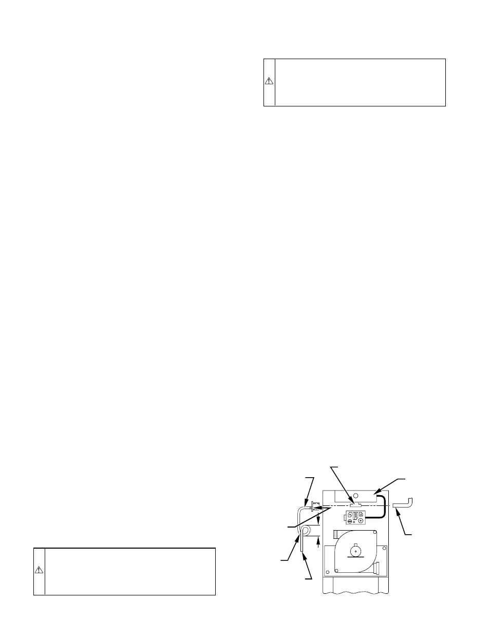
A plugged drain connection has been provided on this
fitting for use when moisture is found in combustion-air
intake pipe and combustion box.
NOTE:
Moisture in combustion-air intake may be result of
improper termination. Ensure combustion-air intake pipe termina-
tion is similar to that shown in Fig. 37, 38, 39, 40, or 41 so it will
not be susceptible to areas where light snow or other sources of
moisture could be pulled in.
If use of this drain connection is desired, drill out fitting’s
tap plug with a 3/16-in. drill and connect a field-supplied
3/8-in. tube. This tube should be routed to open condensate
drain for furnace and A/C (if used), and should be trapped.
(See Fig. 36.)
2. Attach vent pipe as follows:
a. Determine location of vent pipe connection to inducer
housing as shown in Fig. 34 for application.
b. Reposition elastomeric (rubber) inducer housing outlet
cap and clamp to appropriate unused inducer housing
connection. Tighten clamp.
WARNING:
Inducer housing outlet cap must be in-
stalled and fully seated against inducer housing. Clamp
must be tightened to prevent any condensate leakage.
Failure to follow this warning could result in electrical
shock, fire, personal injury, or death.
c. Install pipe support (factory-supplied in loose parts bag)
into selected furnace casing vent pipe hole. Pipe support
should be positioned to bottom of casing hole.
WARNING:
Vent pipe must be installed and fully
seated against inducer housing internal stop. Clamp must
be tightened to prevent any condensate leakage. Failure to
follow this warning could result in electrical shock, fire,
personal injury, or death.
NOTE:
A 2-in. diameter pipe must be used within the furnace
casing. Make all pipe diameter transitions outside furnace casing.
d. Be certain that mating surfaces of inducer housing
connection, elastomeric coupling, and 2-in. diameter
vent pipe are clean and dry. Assemble the elastomeric
(rubber) vent coupling (with 2 loose clamps) onto
inducer housing connection. Insert the 2-in. diameter
vent pipe through the elastomeric (rubber) coupling and
fully into inducer housing connection until it bottoms on
the internal stop. Tighten both clamps to secure the pipe
to inducer housing. Tighten the clamp screws to 15
in.-lb. of torque.
e. Install casing hole filler cap (factory-supplied in loose
parts bag) in unused combustion-air pipe casing hole.
3. Working from furnace to outside, cut pipe to required
length(s).
4. Deburr inside and outside of pipe.
5. Chamfer outside edge of pipe for better distribution of
primer and cement.
6. Clean and dry all surfaces to be joined.
7. Check dry fit of pipe and mark insertion depth on pipe.
NOTE:
It is recommended that all pipes be cut, prepared, and
preassembled before permanently cementing any joint.
8. After pipes have been cut and preassembled, apply gener-
ous layer of cement primer to pipe fitting socket and end of
pipe to insertion mark. Quickly apply approved cement to
end of pipe and fitting socket (over primer). Apply cement
in a light, uniform coat on inside of socket to prevent
buildup of excess cement. Apply second coat.
9. While cement is still wet, twist pipe into socket with 1/4
turn. Be sure pipe is fully inserted into fitting socket.
10. Wipe excess cement from joint. A continuous bead of
cement will be visible around perimeter of a properly made
joint.
11. Handle pipe joints carefully until cement sets.
Fig. 36—Air Intake Housing Plug Fitting Drain
A93035
COMBUSTION –
AIR PIPE
BURNER
BOX
COMBUSTION – AIR
INTAKE HOUSING
3/8" ID TUBE
TRAP
TO OPEN
DRAIN
3/16"
DRILL
4
″
MIN
—28—