E-flite Power 110 Brushless Outrunner Motor, 295Kv User Manual
Page 3
4.
If you add connectors and you no longer wish to use them, never cut the motor wires. Remove them by properly desoldering them. Shortening the motor wires is considered an
improper modification of the motor and may cause the motor to fail.
5.
When you connect the motor to the esc, check the rotation direction of the motor. If you find the rotation is reversed, switching any two motor wires will reverse the direction
so the motor rotates properly.
6.
Proper cooling of the motor is very important during operation. New technology has brought much higher capacity batteries with higher discharge rates, which can cause extreme
motor temperatures during operation. It is the responsibility of the user to monitor the temperature and prevent overheating. Overheating of the motor is not covered under any
warranty.
7.
You can install the propeller on the motor shaft after you have confirmed proper rotation direction, but first make sure it is properly balanced. Also consult the instruction included
with your sensorless electronic speed control for proper adjustments and timing.
8.
Once the battery is connected to the motor, please use extreme caution. Stay clear of the rotating propeller since spinning propellers are very dangerous as the motors produce
high amounts of torque.
9.
Never disassemble the motor. This will void any warranty.
Installation:
NOTE: Photo shows typical installation of motor and x-mount directly to the outside of the firewall. There are other options available including mounting the motor inside the fuselage or
extending the motor further forward using aftermarket mount extensions when using cowls.
1.
You can first trial fit the aluminum x-mount against the front of the firewall and use a Sharpie® to mark the locations of four holes and drill appropriate size hole to fit the blind nuts
provided. Always be sure to maintain the proper thrust line and account for adequate prop/spinner clearance.
2.
Attach aluminum x-mount to the outrunner motor using the four flat head (countersunk) screws provided with the motor.
3.
Install four blind nuts on the inside of the firewall.
4.
Attached the aluminum x-mount and motor to the outside of the firewall using the four socket head bolts and washers.
NOTE: Photo above shows installation using the Evolution™ Standoffs for Gas Engines (part numbers listed above). These standoffs work great for this application and are available in
different sizes from 7mm up to 50mm in length. You can combine them to fit your exact needs. You will need to purchase socket head bolts to fit the customized standoffs lengths. Nylon
motor standoffs (spacers) can also be used.
1.
Attach aluminum x-mount to the outrunner motor using the four flat head (countersunk) screws provided with the motor.
2.
Trial fit the cowl find the standoff length that will allow for proper clearance of your propeller once the cowl is installed.
3.
Insert appropriately sized bolts and washers (purchased separately) into the four outside holes on the x-mount then directly into the Evolution standoffs, or through the standoffs
and then into to blind nuts in the firewall if using hollow motor standoffs/spacers.
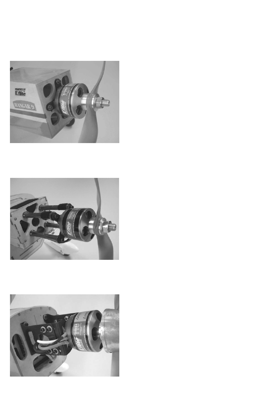
NOTE: Photo shows typical installation of motor directly to a separate electric motor mount such as the Hangar 9® EP Motor Mount with Hardware (HAN4245).