Checking the control throws – E-flite Alpha 450 Sport ARF User Manual
Page 23
23
E-flite Alpha Sport 450 ARF Assembly Manual
Checking the Control Throws
Required Parts
Assembled airframe Transmitter
Motor battery (charged)
The first part of the Checking the Control Throws
section details the basics for setting the control
throws. We at E-flite have also detailed how to
measure the control throws if this is the first time you
have set the control throws for a model aircraft.
1. Turn on the transmitter and receiver of your
model. Check the movement of the rudder using
the transmitter. When the stick is moved right,
the rudder should also move right. Reverse the
direction of the servo at the transmitter if necessary.
2. Check the movement of the elevator with the
radio system. Moving the elevator stick toward the
bottom of the transmitter will make the airplane
elevator move up.
3. Check the movement of the ailerons with the
radio system. Moving the aileron stick right will
make the right aileron move up and the left aileron
move down.
4. Use a ruler to adjust the throw of the elevator,
ailerons and rudder. Adjust the position of the
pushrod at the control horn to achieve the
following measurements when moving the sticks
to their endpoints.
Note: If using the DX5e you will find
your control throws to be slightly
different than listed in the manual on
both high and low rates. The control
throws will work fine as delivered by
the DX5e on both high and low rate.
Aileron Low Rate
Up
1/4-inch
(6mm)
Down
1/4-inch
(6mm)
Aileron high Rate
Up
1/2-inch
(12mm)
Down
1/2-inch
(12mm)
Elevator Low Rate
Up
3/8-inch
(9mm)
Down
3/8-inch
(9mm)
Elevator high Rate
Up
1/2-inch
(12mm)
Down
1/2-inch
(12mm)
Rudder high Rate
Up
1/2-inch
(12mm)
Down
1/2-inch
(12mm)
Measurements are taken at the inner or
widest point on the control surface.
These are general guidelines measured from flight
testing here at E-flite. You can experiment with higher
rates to match your preferred style of flying.
If using a computer radio the Travel Adjust and
Sub Trims are not listed and should be adjusted
according to each individual model and preference.
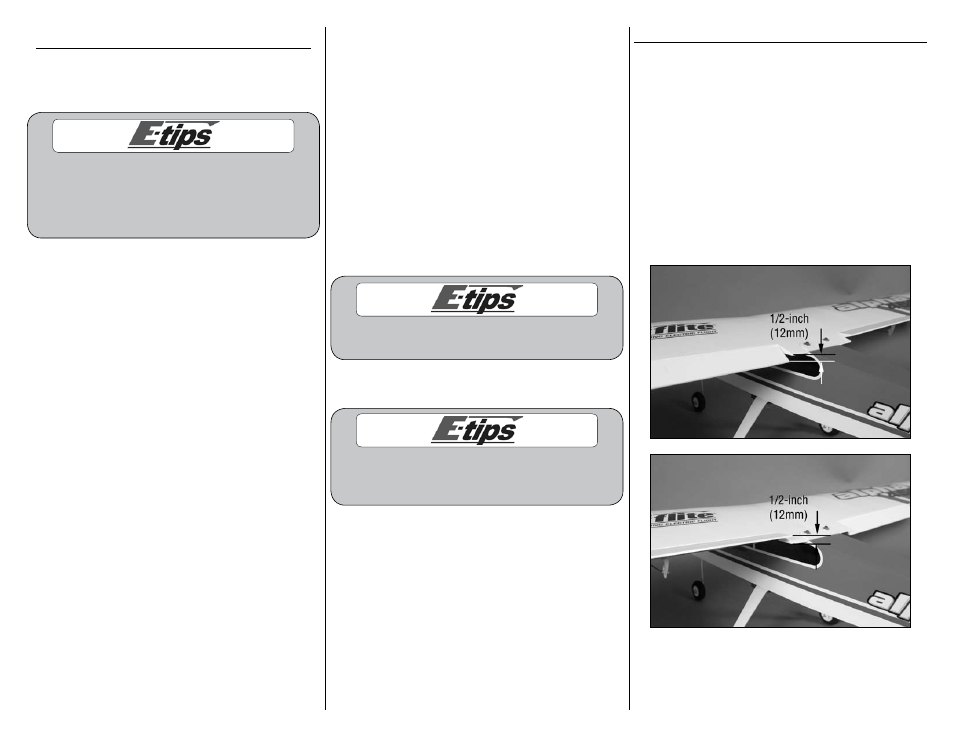
AILERON ThROW
5. Use a ruler to check the control throws on the
ailerons. The dimensions are shown below. For
your reference the aileron pushrods are set up in
the following holes: the middle hole on the aileron
control horn and the outside hole on the aileron
servo arm.
6. From center, use a ruler to measure the movement
of the ailerons. Make sure the ailerons move up
1/2-inch (12mm) from center and down 1/2-inch
(12mm) from center. Measure both the right and left
ailerons to make sure they are working in unison.
This is the setting for the high rate.