Installing the rudder and elevator servos – E-flite Alpha 450 Sport ARF User Manual
Page 11
11
E-flite Alpha Sport 450 ARF Assembly Manual
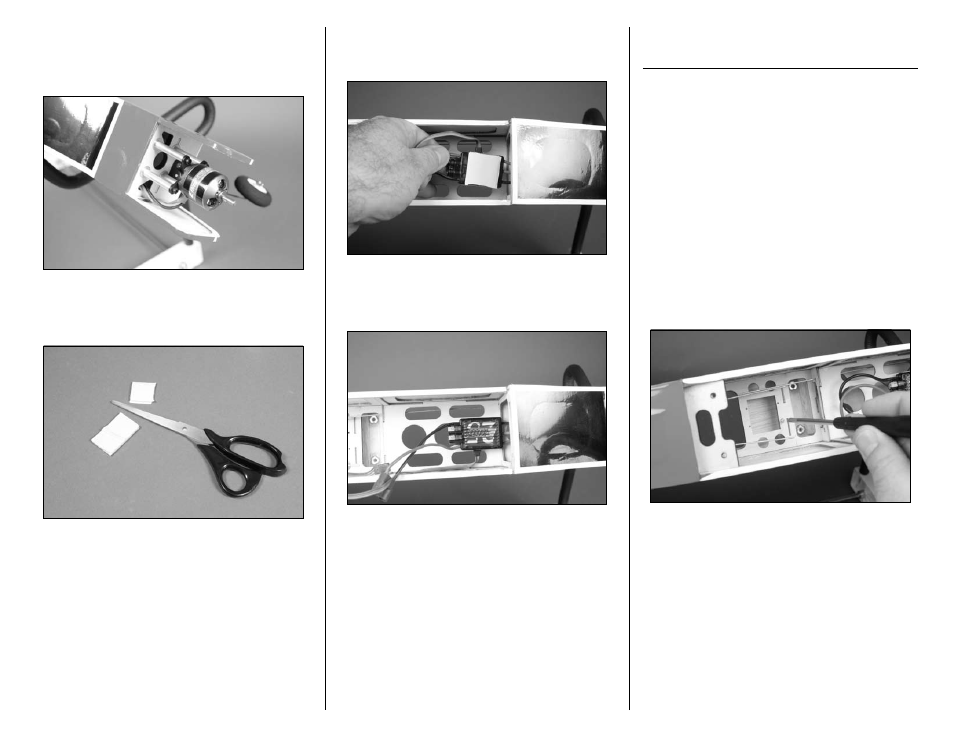
10. Carefully tuck the leads from the motor and
speed control back into the fuselage. This is done
so the leads do not get entangled with the motor or
propeller when flying your model.
11. Use scissors to cut a 1-inch (25mm) piece of
hook and loop material. Use care not to cut your
fingers while cutting the hook and loop material.
12. Remove the backing from one of the pieces of
hook and loop material and apply the hook and
loop to the bottom of the speed control.
13. Remove the remaining backing from the hook
and loop material. Position the speed control in the
fuselage as shown.
Installing the Rudder and
Elevator Servos
Required Parts
Fuselage assembly Servo with hardware (2)
Radio system
2mm x 3mm machine screw (3)
Micro pushrod connector (3)
Micro pushrod connector backplate (3)
Required Tools and Adhesives
Pin drill
Phillips screwdriver: #0, #1
Pliers
Drill bit: 1/16-inch (1.5mm)
Thin CA
Hobby knife with #11 blade
1. Use a #1 Phillips screwdriver to thread one of
the servo mounting screws into each of the four
holes in the servo tray as shown. This will tap the
wood so it can be hardened in the next step.