Motor, speed control and cowling installation – E-flite Rhapsody 25e ARF User Manual
Page 7
7
E-flite Rhapsody 25e ARF Assembly Manual
Motor, Speed Control and
Cowling Installation
Required Parts
Fuselage assembly
Cowling
4-40 x 3/8-inch socket head machine screw (4)
#4 washer (4)
Hook and loop tape
Hook and loop strap (2)
Required Parts (Power 25)
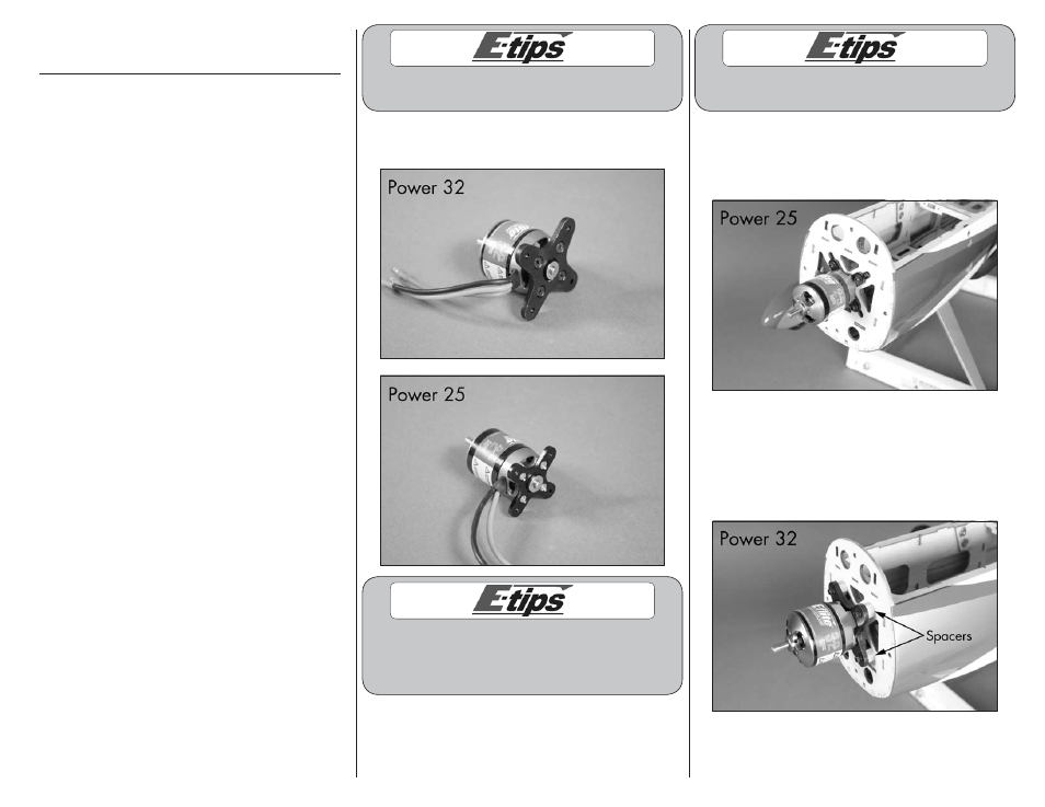
Power 25 brushless outrunner
X-mount with screws
Electronic speed control, 40-amp
4-40 x 3/8-inch socket head screw (4)
#4 washer (4)
Required Parts (Power 32)
Power 32 brushless outrunner
X-mount with screws
Electronic speed control, 60-amp
4-40 x 3/4-inch socket head screw (4)
#4 washer (4)
Aluminum spacer, 1/4-inch (6mm) (4)
Required Tools and Adhesives
Hex wrench or ball driver: 3/32-inch
Phillips screwdriver: #1, #2
Threadlock
Optional Parts
Dummy motor (EFL4539)
Paint Colors for Dummy Radial
Aluminum
Black
Yellow
Light Gray
1. Remove the hatch cover from the top of the
fuselage by lifting the rear of the hatch. The front is
held in place using two dowels.
Make sure to use threadlock on all metal-to-
metal fasteners so they don’t vibrate loose.
2. Use the screws included with the motor to attach
the X-mount to the rear of the motor.
The blind nuts in the firewall for the motor
can be repositioned for a variety of motor
installations. You will need to adjust their position
to suit your particular motor selection.
Make sure to use threadlock on all metal-to-
metal fasteners so they don’t vibrate loose.
3A. Attach the Power 25 motor to the firewall using
four 4-40 by 3/8-inch socket head machine screws
and four #4 washers. Use a 3/32-inch hex wrench
to tighten the screws.
3B. Attach the Power 32 motor to the firewall using
four 4-40 by 3/4-inch socket head machine screws
and four #4 washers. Place the four 1/4-inch
(6mm) aluminum spacers between the mount and
firewall as shown. Use a 3/32-inch hex wrench to
tighten the screws.