Rudder and elevator servo installation – E-flite Rhapsody 25e ARF User Manual
Page 11
11
E-flite Rhapsody 25e ARF Assembly Manual
Rudder and Elevator Servo Installation
Required Parts
Fuselage assembly Nylon clevis (2)
Transmitter
Receiver
Receiver battery
Servo with hardware (2)
Silicone clevis retainer (2)
Pushrod wire, 2-56 x 19
1
/
2
-inch (rudder)
Pushrod wire, 2-56 x 18
3
/
4
-inch (elevator)
Required Tools and Adhesives
Pin vise
Drill bit: 5/64-inch (2mm)
Thin CA
Phillips screwdriver: #1
Side cutter
Ruler
1. Apply 2–3 drops of thin CA in each of the
servo mounting holes to harden the surrounding
wood. This will help in preventing the screws from
vibrating loose.
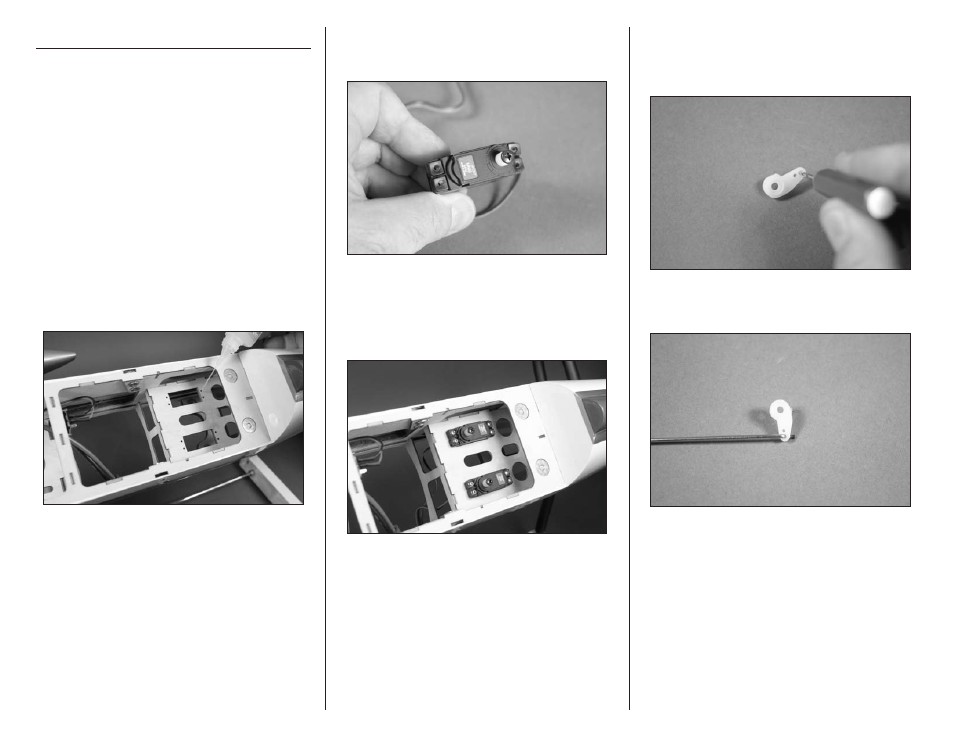
2. Prepare the rudder and elevator servos by
installing the servo grommets and brass eyelets.
Remove the servo horn from the servo as well.
3. Secure the elevator and rudder servos in the
radio tray using the hardware included with the
servo. Use a #1 Phillips screwdriver to tighten the
screws. Note that the output for the servos face to
the front of the fuselage.
4. Use a pin vise and 5/64-inch (2mm) drill bit to
enlarge the hole in the servo horn. Use side cutters
to remove any unused arms so they don’t interfere
with the operation of the servo.
5. Attach the 2-56 x 18
3
/
4
-inch elevator pushrod
wire to the servo horn using the bend in the wire.