E-flite Leader 480 User Manual
Page 9
9
E-flite Leader 480 ARF Assembly Manual
3. Apply 2–3 drops of thin CA in each of the holes
to harden the surrounding wood. This will harden
the threads so the screws do not easily strip the
surrounding wood. Prepare all four mounting holes
at this time.
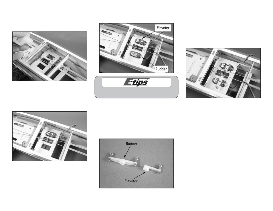
4. Secure the elevator servo in the fuselage using
the screws provided with the servo and a #1 Phillips
screwdriver. The output shaft of the servo faces the
rear of the fuselage when installed. Remove the servo
horn from the servo using a #0 Phillips screwdriver.
5. Repeat step 4 to install the rudder servo in the
fuselage. The output of the rudder servo faces the rear
of the fuselage when installed.
Always use threadlock on metal-to-metal fasteners
to prevent them from vibrating loose.
6. Prepare the rudder and elevator servo horns by
enlarging the outermost hole in a long single-sided
(elevator) or long double-sided (rudder) servo horn
using a pin vise and 5/64-inch (2mm) drill bit. Secure
micro screw-lock connectors to the servo horns using
the hardware provided with the connectors. Make
sure to use threadlock on the nuts to prevent them
from vibrating loose.
7. Use the radio system to center the rudder and
elevator servos. Attach the servo horns prepared
in step 6 on the rudder and elevator servos using
the screw previously removed from the servos and
a #0 Phillips screwdriver. Remove the rubber band
that holds the pushrod in the fuselage. Pass the
pushrod through the connectors and tighten the
screws to prevent the pushrod from falling out of
the fuselage accidentally.