Rudder and elevator installation – E-flite Leader 480 User Manual
Page 19
19
E-flite Leader 480 ARF Assembly Manual
When cutting through the covering, use a
new #11 blade and light pressure to avoid
cutting into the underlying wood, which could
weaken the underlying structure, causing it
to fail in flight. We also recommend using a
hot knife to melt through the covering to help
reduce damaging the underlying wood.
3. Remove the fin from the fuselage. Use a hobby
knife and #11 blade to trim the covering below
the lines drawn in the previous step by 1/16-inch
(1.5mm). Remove the covering, exposing the bare
wood. The lines can be removed using a paper
towel and rubbing alcohol.
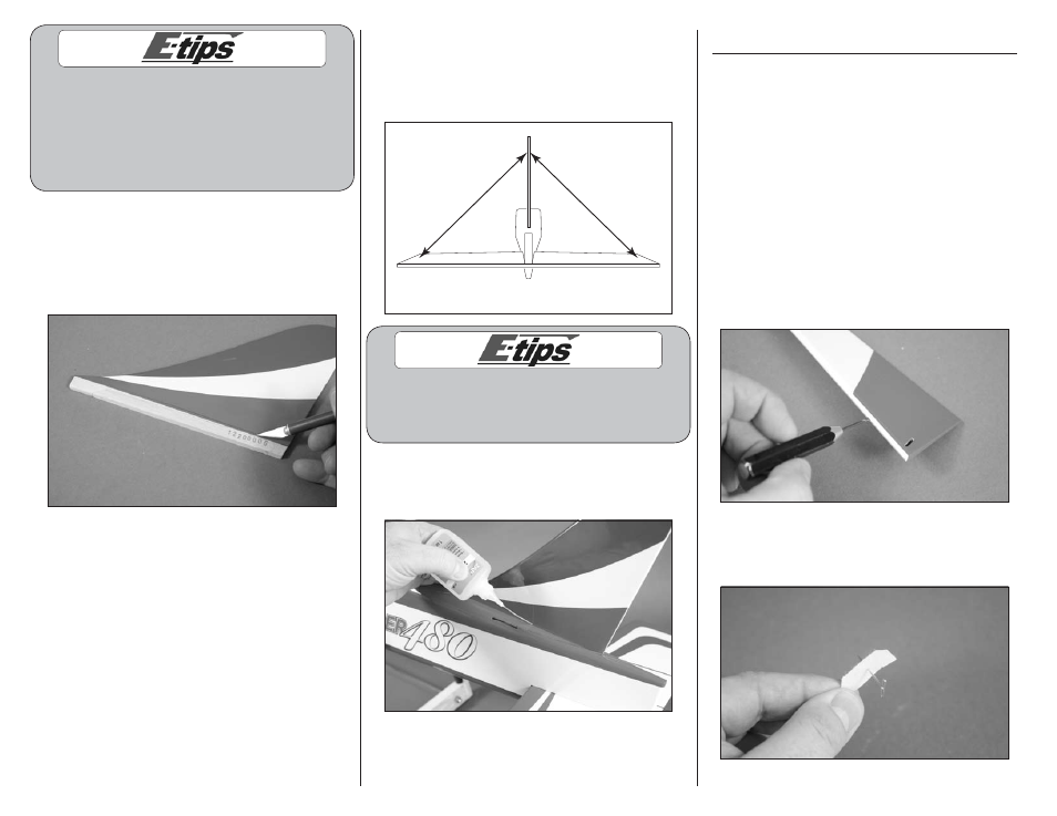
4. Place the fin back in the slot on the top of the
fuselage. Use a square to make sure the fin is
positioned 90-degrees to the stabilizer. If not, lightly
sand the exposed wood on the bottom of the fin to
correct its alignment.
Align 90-degrees
Do not use CA accelerator when gluing the
fin to the fuselage. The CA must be allowed
to soak into the fuselage and fin for the
best bond between the two surfaces.
5. Once aligned, wick thin CA into the joint
between the fin and fuselage. Allow the CA to fully
cure before proceeding.
Rudder and Elevator Installation
Required parts
Fuselage assembly Rudder
Elevator
Control horn with backplate (2)
CA hinge (7)
Required Tools and Adhesives
Thin CA
T-pins
Pin vise
Drill bit: 1/16-inch (1.5mm)
Threadlock
Side cutter
1. Use a pin vise and 1/16-inch (1.5mm) drill bit to
drill a hole in the center of each hinge slot to create
a tunnel for the CA to wick into. This will allow the
CA to penetrate the hinge, creating a better bond
between the hinge and surrounding wood. Prepare
the rudder and fin at this time.
2. Place T-pin in the center of each of the three rudder
(or four elevator) hinges. This will center the hinges
equally in each surface when they are installed.