Rudder and elevator servo installation – E-flite Leader 480 User Manual
Page 8
8
E-flite Leader 480 ARF Assembly Manual
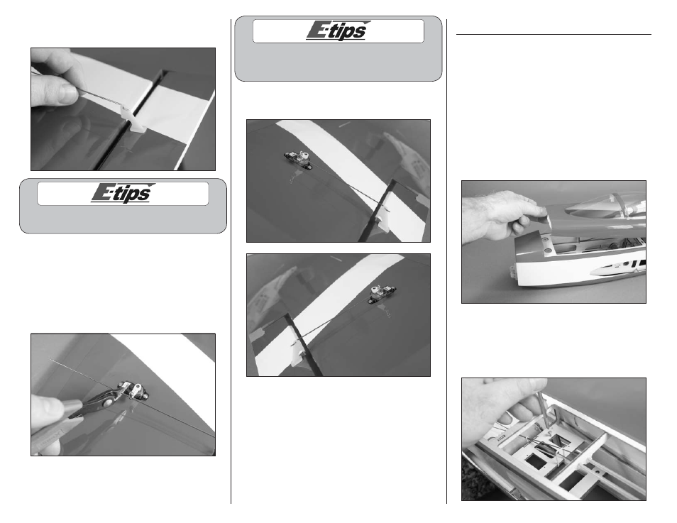
10. Pass the Z-bend in the 1mm x 180mm pushrod
through the outer hole of the aileron control horn.
Always use threadlock on metal-to-metal fasteners
to prevent them from vibrating loose.
11. The pushrod wire will pass through the hole in
the micro screw-lock connector. With the aileron
and aileron servo centered, use side cutters to
trim the pushrod so it is 1/4 inch (6mm) past the
connector as shown. Pass pushrod through micro
screw-lock connector. Use a #1 Phillips screwdriver
to tighten the screw in the connector to secure the
pushrod wire.
Use a small piece of low-tack tape to hold the aileron
in position when installing the linkage. Remove
the tape once the linkage has been installed.
12. Repeat steps 1 through 11 to install the remaining
aileron servo and pushrod.
Rudder and Elevator Servo Installation
Required parts
Fuselage
Servo with hardware (2)
Transmitter
Receiver
Receiver battery
Micro screw-lock connector (3)
Required Tools and Adhesives
Pin vise
Phillips screwdriver: #0, #1
Thin CA
Drill bit: 5/64-inch (2mm)
Threadlock
1. Remove the canopy from the fuselage. Lift the
canopy at the front to disconnect the magnets. The rear
is held in position using tabs that key into the fuselage.
2. Use a #1 Phillips screwdriver to thread a servo
mounting screw into each of the holes to cut threads
in the surrounding wood. Remove the screw before
moving to the next step. Prepare all four mounting
holes at this time.