Motor and speed control installation – E-flite Leader 480 User Manual
Page 12
12
E-flite Leader 480 ARF Assembly Manual
Motor and Speed Control Installation
Required parts
Fuselage assembly Motor with hardware
Speed control
3mm washer (4)
3mm lock washer (4)
Two-sided tape (not included)
6-inch (152mm) servo extension
3mm x 30mm socket head cap screw (4)
Aluminum motor standoff, 18mm (4)
Required Tools and Adhesives
Phillips screwdriver: #1
Hex wrench: 2.5mm
Always use threadlock on metal-to-metal fasteners
to prevent them from vibrating loose.
1. Attach the X-mount to the motor using the
hardware included with the motor and a #1
Phillips screwdriver
2. Secure the motor to the firewall using the four
18mm aluminum motor standoffs, four 3mm x
30mm socket head cap screws, four 3mm washers
and four 3mm lock washers. Use a 2.5mm hex
wrench to tighten the screws. Make sure to use
threadlock on these screws as well to prevent them
from vibrating loose.
3. Place the speed control in the fuselage. It will fit
between the side and sub-side of the fuselage as
shown. Pass the leads for the motor through the
opening at the top of the firewall as shown in the
following step. Use two-sided tape to secure the speed
control in the fuselage.
Matching the colors between the ESC and motor
when they are connected results in the correct
motor direction if using all E-flite components.
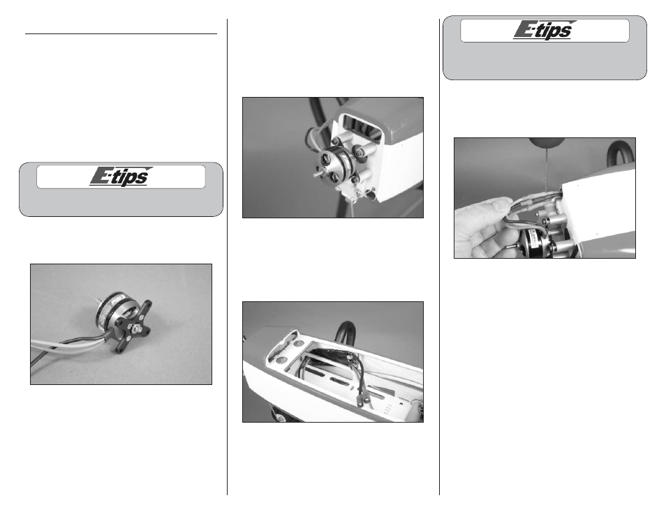
4. Connect the leads from the motor to the speed
control. Once connected, tuck the leads back in the
fuselage to prevent them from interfering with the
operation of the motor.
5. Plug the lead from the speed control into the throttle
port of the receiver at this time.